INFICON TM-400 Thin Film Deposition Monitor User Manual
Page 44
4 - 10
IP
N 17
88
0
0 Re
v.
B
TM-350/400 Operating Manual
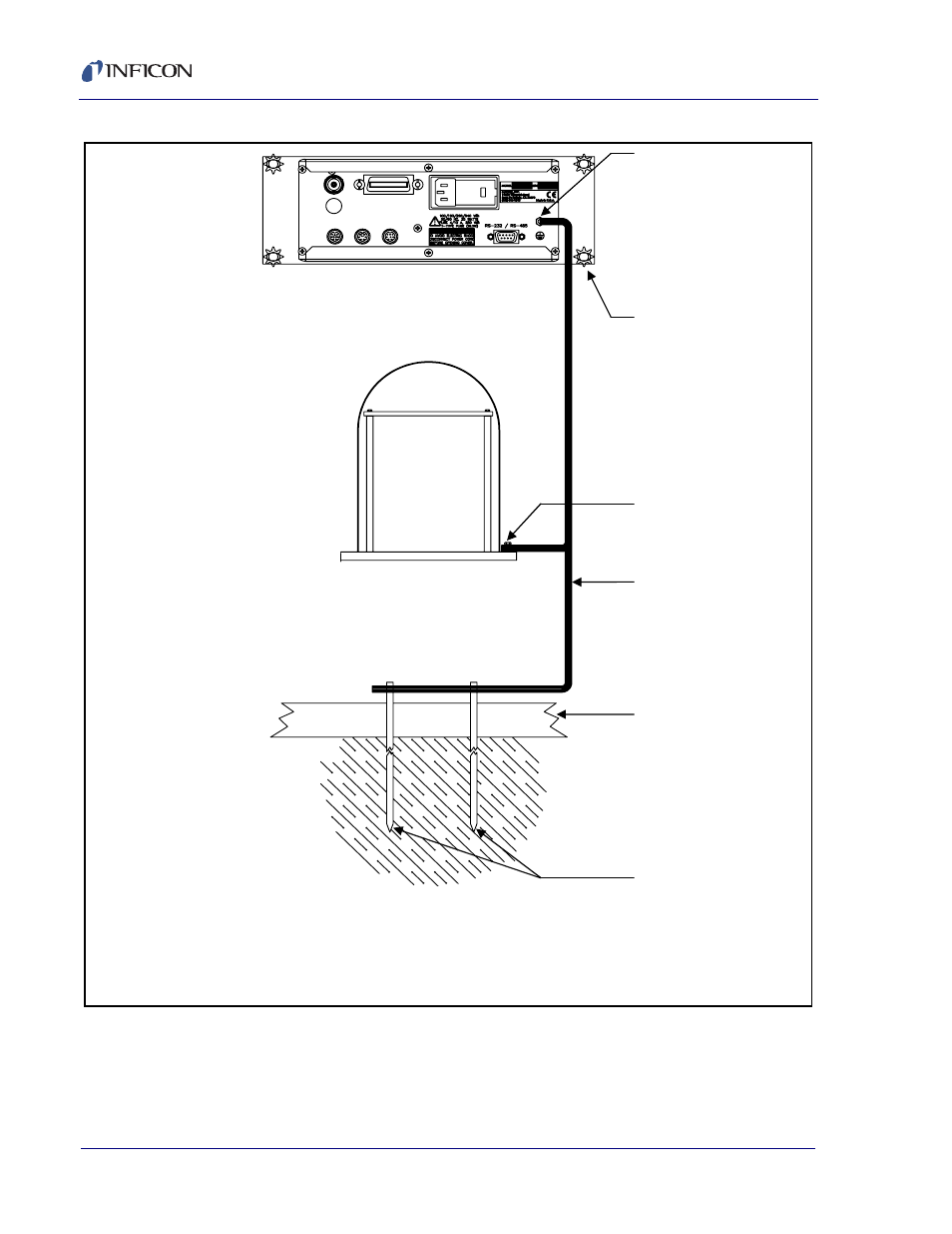
Figure 4-3 Recommended Grounding Method
Star Washers are
recommended to be use
in between the front panel
mounting angles and the
rack. The star washers
will cut through the paint
providing four additional
ground points between
the TM and the instrument
rack.
Bolt copper strap to the
ground lug of the TM
monitor.
System Grounding Point
Bolt copper straps to
clean, bare metal.
Copper Straps should be
as wide as practical,
preferably a 1” copper
sheet or a 1” braid.
Building Floor
Grounding Rods, 6 ft.
apart Copper-clad steel,
¾” dia. x 8 ft. (minimum)
1. As shown, sink two grounding
rods into the earth approximately
six feet apart. Locate these rods
as close as possible to the
vacuum cabinet.
2. Measure the resistance
between the rods. If the
resistance is greater than
3 Ohms, consult an Electrician
specializing in grounding
systems. If the resistance is
3 Ohms or less, connect a length
of copper grounding strap to the
system’s central grounding point,
which should be somewhere on
the vacuum system.
3. Silver solder the other end of
this grounding strap to the rods.
DO NOT rely on mechanical
connections.