Incra wheel kit assembly instructions, Fig. 8 install foot pedal fig. 9 adjustments – INCRA Wheel Kit(New) User Manual
Page 2
MADE IN THE
USA
Manufactured by:
Taylor Design Group, Inc.
P.O. BOX 810262 Dallas, TX 75381
www.incra.com
INCRA Tools are protected by one or more of the following US patents:
#4,793,604, #4,930,221, #5,195,730, #5,275,074, #5,423,360, #5,716,045, #6,237,457,
#6,557,601, #6,672,190. Other patents granted or pending. rev.02.25.08
INCRA is a Registered Trademark of Taylor Design Group
©2007 Taylor Design Group, Inc.
INCRA Wheel Kit Assembly Instructions
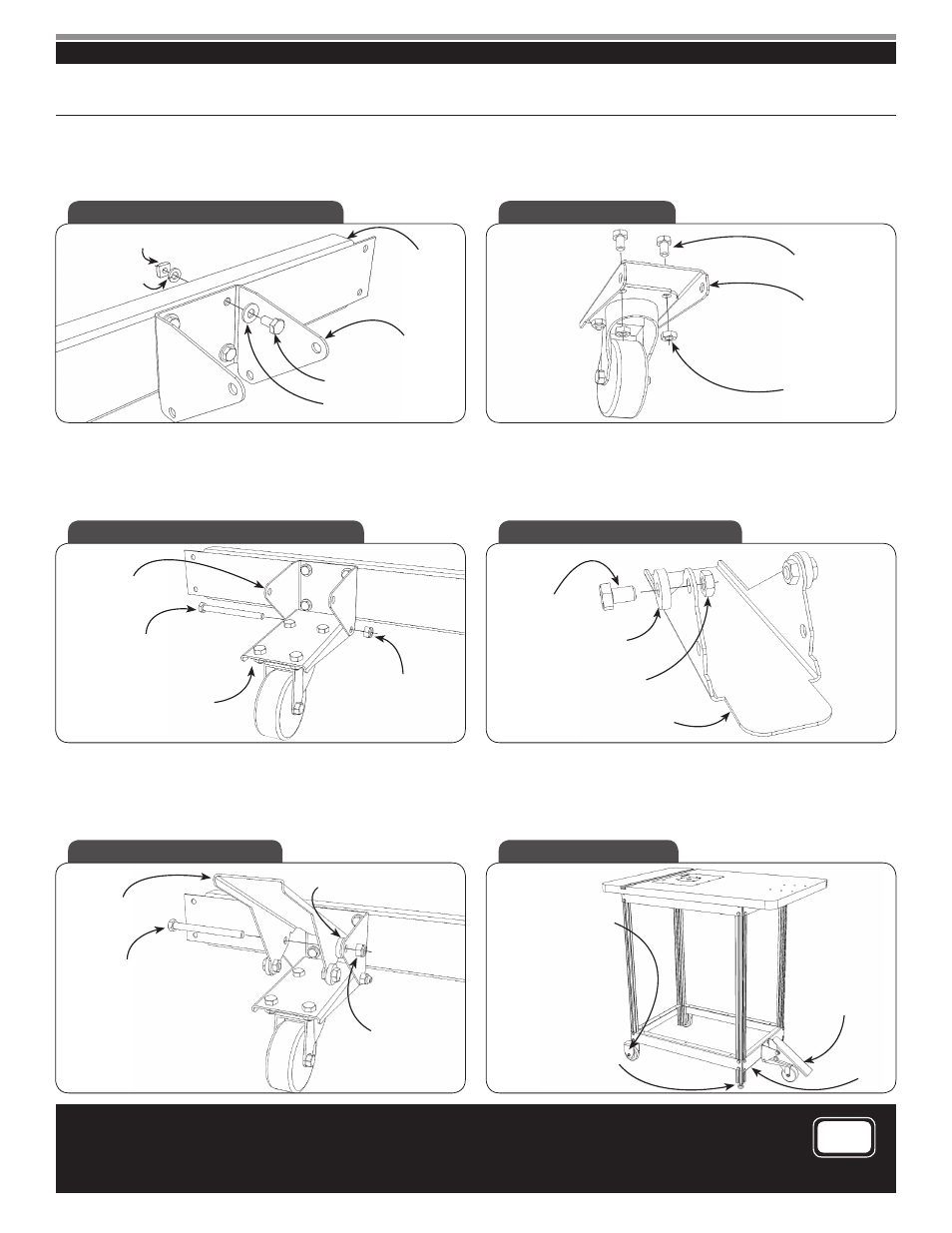
Step 3. Install connector bracket on wheel stringer.
Orient the front wheel connector bracket as shown in
Fig. 4,
then attach it to the wheel stringer using
1/4
-20 x
1/2
hex bolts,
1/4
” washers,
1/4
” lock washers and
1/4
-20 square nuts.
Step 4. Install caster on front wheel pedestal.
Using
5/16
-18 hex bolts and
5/16
-18 hex nuts, attach the swivel
caster to the underside of the front wheel pedestal as shown in
Fig. 5.
Step 5. Attach assembled front wheel pedestal to connector bracket.
Attach the assembled front wheel pedestal to the lower holes in
the connector bracket by using a
5/16
-18 x 3
3/4
hex bolt and
5/16
-18 locking nut,
Fig. 6. The front wheel pedestal must pivot
freely.
Do not overtighten.
Step 6. Install NYLON washers on foot pedal.
Attach two of the
3/16
” thick NYLON washers to the outside of
the foot pedal using
5/16
-18 x
1/2
hex bolts and
5/16
-18 hex nuts
through the holes indicated in
Fig. 7. Tighten securely.
Fig. 4 Install Connector Bracket
Fig. 5 Install Caster
Fig. 6 Install Front Wheel Pedestal
Fig. 7 Install Nylon Washers
Step 7. Attach foot pedal to connector bracket.
Attach foot pedal to the upper holes in the connector bracket
by using a
5/16
-18 x 3
3/4
hex bolt,
5/16
-18 locking nut and two
3/16
” thick Nylon washers,
Fig. 8. The foot pedal must pivot
freely.
Do not overtighten.
Step 8. Operation and adjustments.
Engage the swivel caster by pushing down on the front end of
the foot pedal with your foot. Disengage the caster by pushing
down on the other end of the foot pedal with your foot,
Fig. 9.
Fig. 8 Install Foot Pedal
Fig. 9 Adjustments
1/4
-20 Square Nut
1/4
” Lock Washer
Wheel Stringer
Front Wheel
Connector Bracket
1/4
-20 x
1/2
Hex Bolt
1/4
” Washer
5/16
-18 x
1/2
Hex Bolt
Front Wheel Pedestal
5/16
-18 Hex Nut
Front Wheel
Connector Bracket
5/16
-18 x 3
3/4
Hex Bolt
Assembled Front
Wheel Pedestal
5/16
-18 Locking Nut
5/16
-18 x
1/2
Hex Bolt
3/16
“ Thick Nylon
Washer
5/16
-18 Hex Nut
Foot Pedal
3/16
“ Thick Nylon Washer
Note: TWO washers. One on
each side of foot pedal.
Foot Pedal
5/16
-18 x 3
3/4
Hex Bolt
5/16
-18 Locking Nut
Adjust Vertical Position
of Leg Wheels for
Stability
Adjust the height of the
wheel stringer and the
leg levelers on either
side of the swivel caster
so that the leveler pads
are OFF the floor when
the foot pedal is en-
gaged, and on the floor
when the foot pedal is
disengaged.
Push foot pedal
down here with your
foot to engage the
swivel caster.
Push other end to
disengaged.
Wheel
Stringer
2