Hydaclab, Electrical connections – HYDAC HLB 1400 User Manual
Page 7
Instruction Manual HYDACLab
®
03.03.2008
7
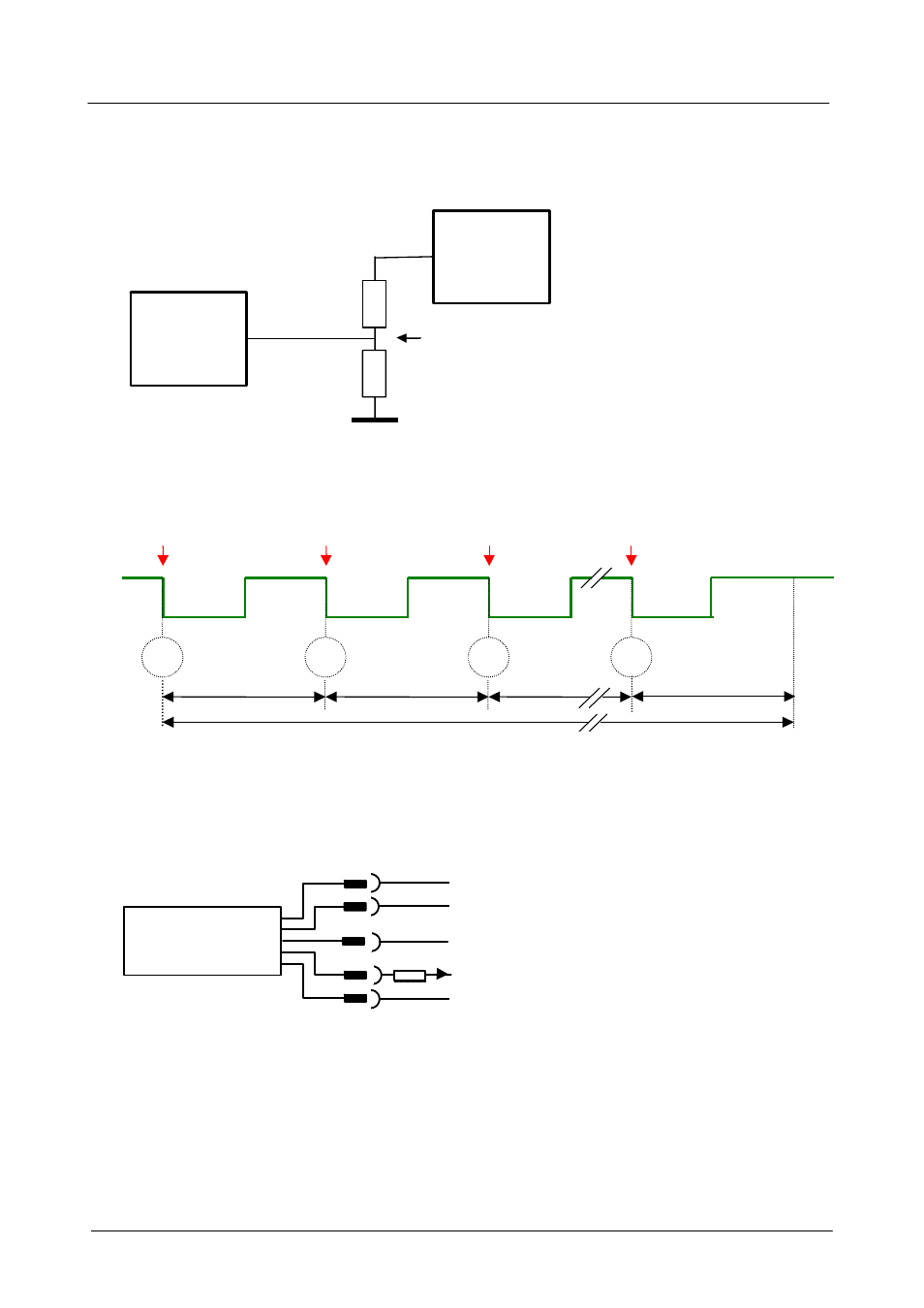
6.2 Reset via PLC control
To connect the HYDACLab
®
to the PLC control a voltage divider must be provided on the PLC
switch output as per the diagram below.
Over a period of 8s the HYDACLab
®
detects a cycle of high-low pulses and resets the sensor.
In normal operating conditions, the level at PIN 5 must be 12 VDC
± 0.5 V.
1
2
3
1s
1s
8
1s
8s
1s
+12V DC
Once the unit has been reset, the status signal indicates the value 5mA.
7. Electrical Connections
Signal 1
HYDACLab
2
1
3
4
+U
B
Signal 2
RL
5
GND
Signal 1: PNP switch output
Signal 2: Sequential analogue output (4 .. 20 mA)
HSI* / Reset (PLC)
PIN 5:
HSI channel / reset (PLC)
R
Lmax
= (U
B
-5V) / 20mA [k
Ω] and R ≤ 500 Ω
Note:
The load resistance R
L
is the sum of the internal input resistance of the evaluation unit and the
resistance of the connection lines.
* HSI = HYDAC Sensor Interface (HYDAC internal communication interface)
U
PLC
PLC
HLB1 000
Pin 5
R
2
R
1
12 VDC
±0.5V