HYDAC HLB 1400 User Manual
Page 5
Instruction Manual HYDACLab
®
03.03.2008
5
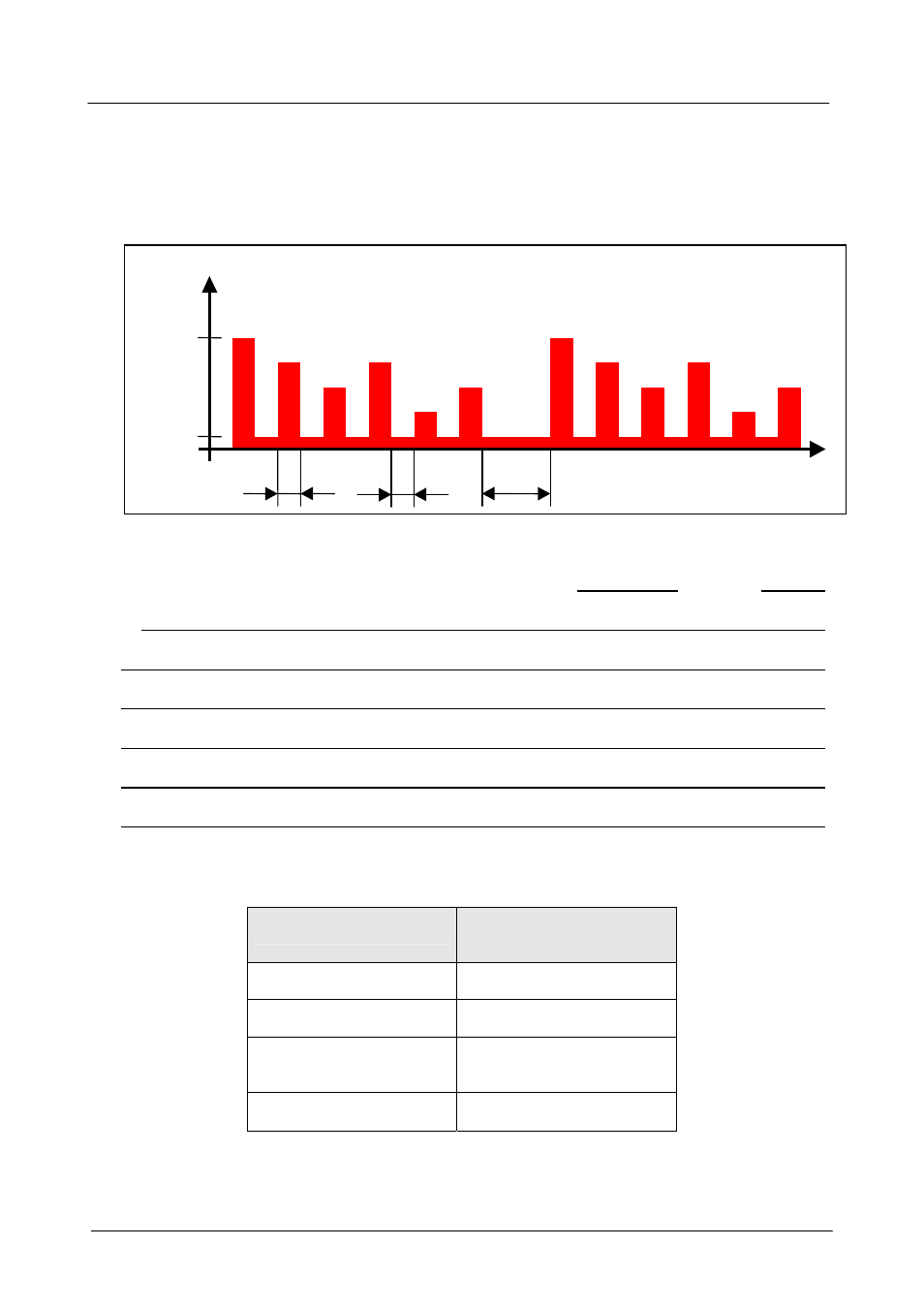
4.2 Analogue Output
Analogue output signals representing measured values are output sequentially to Pin 4, when
synchronization with the controller interfaced to the sensor is required.
The sequencing of the signals involved is as shown in the diagram below:
All signals output to the analog output are 4 .. 20 mA current-loop signals, sequenced
and spaced as follows
Output
signal Duration
Start signal:
20 mA
2 s
______________________________________________ Pause (4 mA)
2 s
Signal 1:
Relative change in viscosity
-30% ... +30%
2 s
Pause (4 mA)
2 s
Signal 2:
Relative change in dielectric constant
-30% ... +30%
2 s
Pause (4 mA)
2 s
Signal 3:
Relative humidity
0% ... +100%
2 s
Pause (4 mA)
2 s
Signal 4:
Temperature
-25°C... +100°C
2 s
Pause (4 mA)
2 s
Signal 5:
Status signal
See table below for levels
2 s
Pause before next output cycle:
4 mA
30 s
Explanation of status signal:
Status
Status signal
(mA)
Referencing phase
5
Operating phase
7
Fluid condition out
of range
9 or 11
Internal error
≥ 13
Note:
Due to possible tolerances, we recommend setting the threshold in the evaluation electronics approx. 0.25 mA below the
ideal value given in the table.
t
Start
Rel.
visc.
Rel.
DC
Rel.
humidity
Temp.
Status
Start
20mA
4mA
I
2s
30s
2s