Notice – Heidolph ROTAVAC 20 User Manual
Page 17
Documents are only to be used and distributed completely and unchanged. It is strictly the users´ responsibility to check carefully
the validity of this document with respect to his product. Manual-no.: 01-005-005-36-1
page 17 of 35
Translation of the original instructions
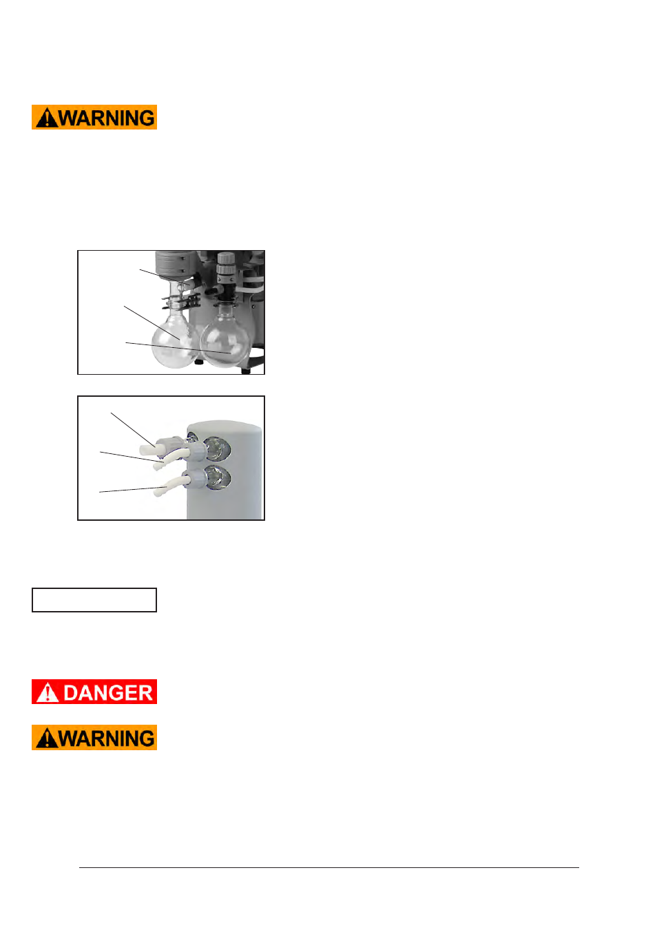
(2)
outlet (gas!; hose nozzle 8-10 mm)
(1)
Attach the pipelines of the coolant circuit to the respective hose nozzles (hose noz-
zles 6-8 mm, see image) at the waste vapor condenser.
Check hose connections prior to starting operation of the cooling system.
Secure coolant hoses at the hose nozzles (e.g. with hose clip) to prevent their ac-
cidental slipping.
➨ If necessary connect the exhaust to a suitable treatment plant to prevent the dis-
charge of dangerous gases and vapors to the surrounding atmosphere.
+ The gas outlet (hose nozzle 8-10 mm) must not be blocked. The exhaust pipeline
has always to be free and pressureless to enable an unhindered discharge of
gases.
Catchpots:
The catchpot at the inlet protects against droplets and parti-
cles from entering the pump.
+ Enhances lifetimes of diaphragms and valves.
+ Improves vacuum performance in applications with con-
densable vapors.
Both catchpots are coated with a protective layer to protect
against shattering in case of breakage or implosion.
➨ Assemble the catchpots at the inlet and at the outlet using
joint clips.
overpressure
safety relief
device
catchpot
at outlet
catchpot
at inlet
Exhaust waste vapor condenser:
➨ Assemble hose nozzles for coolant inlet (1) and coolant
outlet (2) pipelines at the exhaust waste vapor condens-
er.
The exhaust waste vapor condenser
enables an efficient
condensation of the pumped vapors at the outlet.
+
No backflow of condensates.
+ Controlled recovery of condensates.
+ Next to 100% solvent recovery.
+ The isolation cover protects against glass splinters in case
of breaking, acts as thermal isolation to avoid condensa-
tion of humidity and is intended to absorb shocks.
NOTICE
4.2 Exhaust waste vapor condenser and separator
+
Check glass parts for damage and bracing.
Use only faultless glass parts.
Assembling the hose nozzle with union nut:
- Take the hose nozzle with attached compression ferrule and union nut out of the
catchpot and put onto inlet connection
- Tighten the union nut by hand until you can feel the stop. Then tighten an addi-
ighten the union nut by hand until you can feel the stop. Then tighten an addi-
tional 1/4 rotation with an open-ended wrench (size 17mm) for final installation.