Installation instructions, Instrucciones de instalación – Graff WALL-MOUNTED BATH MIXER User Manual
Page 6
4
5
R2
5
3
4
2
1
A
3
Finished W
all
Acabado de la pared
~1-21/32"(42mm
)
4.2
4.3
4.1
Hot Water Inlet
Entrada
de Agua Caliente
Cold Water Inlet
Entrada
de Agua Fría
9&10
6
R7&R8
R7&R8
R5&R6
R
16
15
ESPAÑOL
ENGLISH
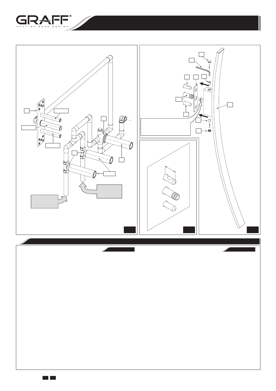
SPOUT INSTALLATION
•
INSTALACIÓN DEL CAÑO
VERSION 2 /see fig. 3.2/: Total wall thickness (T):
MIN. 2”- MAX. 3” /marble wall/
➣
cut the mounting pins (R3) using hack-saw so that the
two pins protrude from the finished wall by about 0.2”
(5mm); remove all burrs after cutting,
➣
ATTENTION! Do not cut spout connection (R2).
5. Screw mounting sleeves
(5) onto the pins (R3) until re-
sistance is felt /see fig. 4.3/. ATTENTION! The distance
from the finished wall to the tip of sleeve (5) should
be about 1-21/32” (42mm) /see fig. 4.2/. Top sleeve
(5) should be positioned in such way that the tapered
recess is pointing upwards, and the bottom sleeve
(5)
should be positioned in such way that the tapered recess
is pointing downwards /see fig. 4.2/.
6. Put the washer
(2) onto the mounting sleeves (5).
7. Screw the fixing screws
(3) 1-1.5 turns into appropriate
sockets in spout holder /see fig. 4.3/. Use the hex key
(A).
8. Slide the spout
(1) over two mounting sleeves (5) and
spout connection
(R2), pay attention that the washer (2)
is correctly positioned.
9. Holding the spout
(1) screw all the way in both of fixing
screws (3) using the hex key (A).
10. Put in the masking caps
(4) into spout holder.
VARIANTE 2 /ver el dis. 3.2/: Espesor total del muro (T):
MIN. 2” – MAX. 3” /la pared de mármol/
➣
corte los pernos de montaje (R3) con el serrucho para me-
tal de tal modo que los pernos emerjan de la cara interior
de la pared de acabado de unos 0,2” (5mm); elimine todas
las rebabas que se puedan producir en el momento de cor-
tar,
➣
ATENCIÓN: No corte la conexión del caño (R2).
5. Sobre los pernos de montaje (R3) enrosque los casquillos de
montaje (5) girándolos a tope /ver el dis. 4.3/. ATENCIÓN:
La distancia entre la parte frontal de la pared de aca-
bado y la parte frontal del casquillo (5) debe de ser de
unos 1-21/32” (42 mm) /ver el dis. 4.2/. Ponga el casquillo
superior (5) de tal manera que el recorte cónico esté dirijido
hacia arriba, mientras el casquillo inferior (5) ponga de tal
manera que el recorte esté dirijido hacia abajo /ver el dis.
4.2/.
6. Sobre los casquillos de montaje (5) enroscados ponga la aran-
dela (2).
7. Apriete de un 1-1,5 giro los tornillos de fijación (3) en los
asientos adecuados en la parte de montaje del caño /ver el dis.
4.3/. Use la llave alien (A).
8. Coloque el caño (1) sobre dos casquillos de montaje (5) y la
conexión del caño (R2). Preste atención a posicionar correc-
tamente la arandela (2).
9. Sosteniendo el caño (1) apriete a tope ambos tornillos de fija-
ción (3) con la llave alien (A).
Make sure that the Teflon
®
insert is
in a proper position in the spout holder.
Asegúrese que el insertador de Teflon
®
se encuentren en su lugar en el parte
de montaje del caño.
6
IOG 2330.50
Rev. 1 July 2008
GB E
Installation Instructions
●
Instrucciones de Instalación
WALL-MOUNTED BATH MIXER
EL GRIFO DEL BAÑO DE MONTADOS EN LA PARED