Graff WALL-MOUNTED BATH MIXER User Manual
Page 12
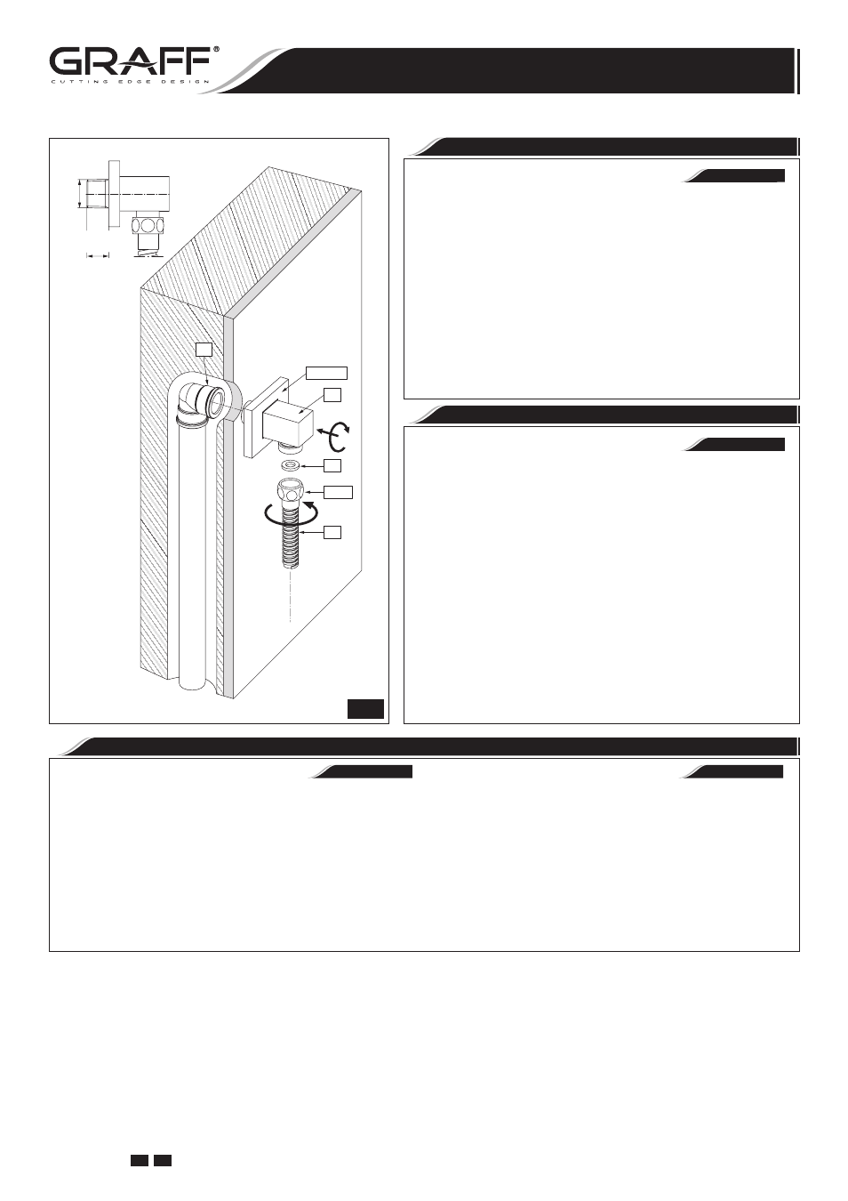
1/2"NPT
MAX. 5/8"
(MAX. 16mm)
23&24
26.2
22
25
26
G
9
See fig. 9.
•
Slide the escutcheon (23) with rubber insert (24) over the
supply elbow (22). Apply Teflon
®
tape to threaded end of
supply elbow (22) and thread into riser elbow (G), making
sure that supply elbow outlet is in a downward facing position.
Slide the escutcheon
(23) with rubber insert (24) against the
finished wall.
•
Seat the flat seal (25) firmly into the hose nut (26.2). Attach
the shower hose to the threaded supply outlet.
CAUTION: To avoid damage the supply elbow or hose finish dur-
ing installation, wrap with a cloth or tape and use only a smooth-
jawed wrench. Do not overtighten connections.
ENGLISH
SUPPLY ELBOW INSTALLATION
Ver dis. 9.
•
Deslice con cuidado el chapetón (23) y el inserto de goma
(24) sobre el codo de abastecimiento (22). Aplique cinta
Teflon
®
a las puntas roscadas de la codo de abastecimiento
(22) y enrósquelo en el codo del tubo (G) asegurándose que
la toma del codo de abastecimiento de agua quede en posi-
ción cara hacia abajo. Deslice con cuidado el chapetón
(23) y
el inserto de goma (24) contra la pared de acabado. vertical
de suministro.
•
Coloque la junta plana (25) firmemente dentro de la tuerca
de la manguera (26.2). Fije la manguera de la regadera a la
toma de agua enroscada.
ADVERTENCIA: Para evitar daños del codo de abastecimiento
o el acabado de la manguera durante la instalación, protejálos
con un trapo o una cinta y use solamente la llave de tuercas con
mordaza lisa. No apriete demasiado las conexiones.
ESPAÑOL
MONTAJE DEL CODO ABASTECEDOR
See fig. 10.
The water flow is opened using the handle. It is opened fully
by turning the handle in counterclockwise direction. The in-
tensity of the water flow is regulated by positions between
0° ÷ 90° angle.
Turning the handle of diverter valve in counterclockwise direction
causes the water to flow out through the spout. Turning the handle
in clockwise direction causes the water to flow out through the
shower handset.
Ver dis. 10.
Para abrir la salida de ajuste de temperatura use la manilla.
La apertura completa/maxima obtiene girando la manilla a la
izquierda. La regulación de la intensidad del flujo de agua
sucede en las posiciones entre 0° ÷ 90°.
Girando la manilla de válvula del desviador a la izquierda causa
la salida del agua por el caño, girando la manilla a la derecha
causa la salida del agua por el regadera de mano.
ESPAÑOL
ENGLISH
OPERATING INSTRUCTIONS
•
DESCRIPCIÓN DEL FUNCIONAMIENTO
12
IOG 2330.50
Rev. 1 July 2008
GB E
Installation Instructions
●
Instrucciones de Instalación
WALL-MOUNTED BATH MIXER
EL GRIFO DEL BAÑO DE MONTADOS EN LA PARED