Graff WALL-MOUNTED WASH-BASIN MIXER User Manual
Page 7
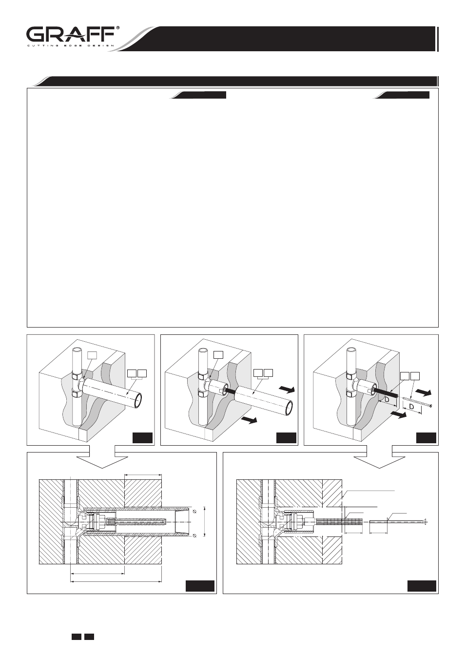
CUT
CORTE
CUT
CORTE
FINISHED WALL
ACABADO DE LA PARED
~0.2" (~5mm)
D
D
5.3.1
MAX. 1-21/32" ( 42mm)
(MOUNTING HOLE)
MAX. 2-3/32"
MIN. 3-1/32" (77mm)
MAX. 5-1/8" (130mm)
6
9 10
6
9 10
5.2
5.1
7 8
5.3
5.1.1
6. Insert handle base (11) to mounting hole until snug
against finished wall. Position handle base (11) so that
hex set screw (12) is located at the bottom of handle base
(11). The handle base should be positioned like is shown
on fig. 5.5.
7. Measure from the end of sleeve (13) the same length
(D) as in stem extension (7) and screw (8), then cut
the sleeve (13) using hack-saw at the marked-up place.
Screw the sleeve (13) into valve (6) using provided hex
key (C), make sure that the handle base (11) is correctly
located on the wall, tighten the sleeve (13) – see fig.
5.6.
8. Put the hex key (B) into the hole of the slide ring (S) in
handle (14) and rotate the ring (S) so that the hole in the
ring is in bottom position facing the hex set screw (12) in
the handle base (11) – see fig. 5.7. Remove the hex key
(B) from the hole and push in the handle assembly (14)
onto stem extension (7) – see fig. 5.7. Set the handle
(14) as on fig. 1 “OFF” position.
9. Block carefully the handle (14) with a set screw (12) us-
ing the hex key (included with the mixer) – see fig. 5.8.
A screw pin should enter the hole in the slide ring (S). In
case of excessive pressure and difficulties with rotation of
the handle loosen up the set screw (12) by a 1⁄4 turn.
Repeat steps for second valve and handle.
6. Coloque la base de la manilla (11) en el agujero de mon-
taje hasta que toque la pared de acabado. Coloque la base
de la manilla
(11) de tal modo que el tornillo haxagonal
(12) se encuentre en la parte baja de la base de la manilla
(11). La base de la manilla (11) debe instalarse tal como
se indica en el dis. 5.5.
7. Partiendo del fin del casquillo (13) la misma distancia (D)
que en caso de la extensión de espiga (7) y tornillo (8),
luego corte el casquillo (13) en el lugar marcado con un
serrucho para metal. Enrosque el casquillo (13) en la vál-
vula (6) con una llave allen (C) adjuntata prestando aten-
ción a la posición correcta de la base de la manilla (11) en
la pared, apriete el casquillo (13) - ver dis. 5.6.
8. Ponga la llave hexagonal en el agujerito del anillo de des-
lizamiento (S) en la manilla (14) y gire todo el anillo (S)
hasta el punto donde el agujerito del anillo se encuentre al
frente del tornillo hexagonal (12) en la base de la manilla
(11) - ver dis. 5.7. Quite la llave hexagonal del agujerito
y ponga el juego de manilla (14) en la extensión de es-
piga (7) - ver dis. 5.7. Ponga la manilla (14) como en el
dis. 1 en la posición “OFF”.
9. Bloquee con cuidado la manilla (14) con el tornillo (12)
usando la llave hexagonal (que va junto con el grifo) - ver
dis. 5.8. El gorrón del tornillo tiene que entrar en agujerito
del anillo de deslizamiento (S) de la manilla. En el caso de
una presión demasiado grande que dificulte la rotación de
la manilla, afloje el tornillo (12) a 1⁄4 de su rotación.
Repita los pasos descritos para otra válvula y manilla.
ESPAÑOL
ENGLISH
VALVE & HANDLE INSTALLATION
•
INSTALACIÓN DE LA VÁLVULA Y LA MANILLA
7
IOG 2330.00
Rev. 1 June 2008
GB E
Installation Instructions
●
Instrucciones de Instalación
WALL-MOUNTED WASH-BASIN MIXER
EL GRIFO DEL LAVABO DE MONTADOS EN LA PARED