Three hole basin mixer – Graff THREE HOLE BASIN MIXER User Manual
Page 3
2
c u t t i n g e d g e d e s i g n
Instructions for assembly and use • Montage- und Gebrauchsanweisung • Notice technique montage et utilisation • Инcтрукция по монтажу и обслуживанию • Instrucción de Montaje y Servicio • Manuale di Montaggio e Uso
3-LOCH-HANDWASCHBECKEN-MISCHBATTERIE
BATTERIE DE LAVABO À TROIS TROUS • СМЕСИТЕЛЬ ДЛЯ УМЫВАЛЬНИКА С 3-МЯ ОТВЕРСТИЯМИ
LAVABO GRIFO 3-AGUJERO • BATTERIA LAVABO A 3 FORI
3
IOG 2341.20
Rev. 1 April 2010
GB D
F RUS E
I
THREE HOLE BASIN MIXER
19
Threaded ferrule
Gewindestutzen
Tubulure filetée
Резьбовой патрубок
Conectador roszado
Tubo di giunzione filettato
20
Locknut
Befestigungsmutter
Écrou de fixation
Крепёжная гайка
Contratuerca
Dado di fissaggio
21
Supply hose 450mm
Zulaufschlauch 450mm
Tuyau d’alimentation 450mm
Питающая трубка 450мм
Manguera suministro 450mm
Flessibile di alimentazione 450mm
22
Lift rod
Zugstange
Tige d’ouverture du bouchon
Пруток шатуна
Varilla elevadora
Asta del tirante
23
Lift rod base
Zugstangenunterbau
Base de la tige d’ouverture du bouchon
Основание прутка шатуна
Base de la varilla elevadora
Base dell’asta del tirante
24
Washer
U-Scheibe
Rondelle
Шайба
Arandela
Rondella
25
Metal washer
Metallscheibe
Rondelle en métal
Металлическая шайба
Arandela de metal
Rondella di metallo
26
Nut
Mutter
Écrou
Гайка
Tuerca
Dado
27
Sleeve
Hülse
Douille
Втулка
Casquillo
Boccola
28
Nut
Mutter
Écrou
Гайка
Tuerca
Dado
GB
D
F
RUS
E
I
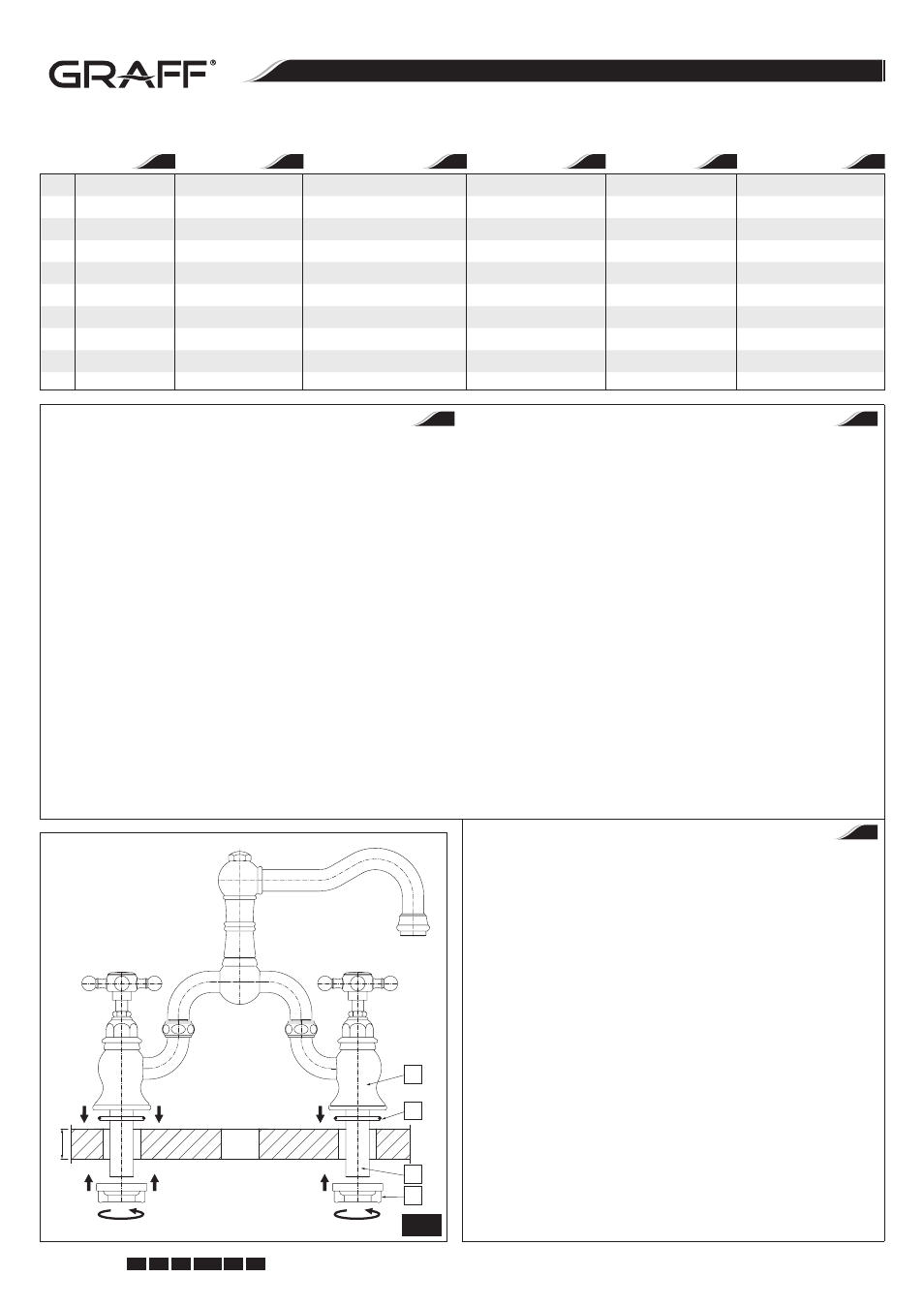
MIXER INSTALLATION - see fig. 2, 3.1-3.3
1. Prepare mounting holes according to fig. “Installation Diagram”, page 1.
2. Loosen up the nuts (9).
3. Insert the mixer into the fitting holes of the sink.
4. Place mixer into proper position on sink. Make sure that the o-ring seals
(18) sit correctly in their own housing in the body of mixer (1).
5. Check the mixer position and secure in place using the locknuts (20).
Hand tighten only. Do not over-tighten.
6. Tighten the nuts (9).
7. Unscrew the nut (28) with rubber sleeve (27) and the nut (26) from the
shank of lift rod base (23). Remove metal washer (25) and the washer
(24).
8. Insert the lift rod base (23) through the mounting hole from above. If
the mounting surface is uneven, apply a bead of plumbers putty or other
sealant to the underside of the base (23).
9. From the underside of the sink, slide the washer (24), metal washer (25)
and screw the nut (26) onto the escutcheon shank. Securely tighten the
nut (26) with a wrench. Do not overtighten.
10. Remove any excess putty or sealant from underside of the base (23).
11. Screw the nut (28) with rubber sleeve (27) on to the base shank (23).
12. Insert the lift rod (22) into the hole of the base (23) and tighten the nut
(28) if needed.
MONTAGE DER MISCHBATTERIE - siehe Abb. 2, 3.1-3.3
1. Montageöffnungen gemäß Abb. „Montageschema“, Seite 1 vorbohren.
2. Muttern (9) lösen.
3. Mischbatterie in vorgesehene Bohrungen in der Montagefläche einsetzen.
4. Mischbatterie richtig auf der Montagefläche positionieren.
Sicherstellen,dass O-Ringe (18) richtig im Versatz des Mischbatteriekör-
pers (1) positioniert sind.
5. Korrekte Lage der Mischbatterie prüfen und Befestigungsschrauben (20)
festschrauben. Die Muttern nur manuell nachziehen.
6. Muttern (9) nachziehen.
7. Mutter (28) mit Gummihülse (27) und Mutter (26) vom Endstück des
Zugstangenunterbaus (23) abschrauben. Metallscheibe (25) und
U-Scheibe (24) entfernen.
8. Zugstangenunterbau (23) von oben in die Montageöffnung stecken. Ist
die Montagefläche uneben, untere Seite des Zugstangenunterbaus (23)
mit einer kleinen Menge Silikondichtmittel versehen.
9. U-Scheibe (24), Metallscheibe (25) von der unteren Seite des Hand-
waschbeckens auf den Stutzen des Zugstangenunterbaus schieben und
Mutter (26) vorsichtig mit einem Universalschlüssel nachziehen.
10. Überschüssiges Silikondichtmittel vom Zugstangenunterbau (23) entfer-
nen.
11. Mutter (28) mit Gummihülse (27) auf den Stutzen des Zugstangenunter-
baus (23) schrauben.
12. Zugstange (22) in die Öffnung im Zugstangenunterbau (23) schieben
und gegebenenfalls Mutter (28) nachziehen.
MONTAGE DE LA BATTERIE - voir schéma 2, 3.1-3.3
1. Préparez les trous de montage conformément au dessin «Schéma de
montage», pa ge 1.
2. Donnez du jeu aux écrous (9).
3. Placez la batterie dans les orifices préparés sur la surface de montage.
4. Placez la batterie dans la bonne position sur la surface de montage.
Assurez-vous que les rondelles de type o-ring (18) se trouvent à la bonne
place, au niveau des entailles du corps de la batterie (1).
5. Vérifiez le positionnement correct de la batterie et vissez les écrous
de fixation (20). Ces écrous doivent être serrés à la main.
6. Serrez les écrous (9).
7. Dévissez l’écrou (28) avec la douille en caoutchouc (27) et l’écrou (26) de
la tubulure de la base de la tige du mécanisme d’ouverture du bouchon
(23). Retirez la rondelle en métal (25) et la rondelle (24).
8. Placez la base de la tige (23) en l’introduisant par le haut de l’orifice de
montage. Si la surface de montage est inégale, lubrifiez le fond de la base
(23) avec un peu produit au silicone assurant l’éctanchéité.
9. Par en-dessous (sous le lavabo), placez la rondelle (24), la rondelle en
métal (25) et vissez l’écrou (26) sur le manchon de la base. Serrez avec
précaution l’écrou (26) à l’aide d’une clef à ouverture variable.
10. Enlevez du dessous du socle (23) l’excédent de produit au silicone assu-
rant l’étanchéité.
11. Vissez l’écrou (28) et la douille en caoutchouc (27) sur la tubulure
du socle (23).
12. Placez la tige du mécanisme d’ouverture du lavabo (22) dans l’orifice situé
sur le socle de la tige (23) puis serrez l’écrou si cela s’avère nécessaire (28).
GB
D
1
18
19
20
MAX
. 35mm
F
2