Pbx gr ound st ar t tr unk t r, Bogen, Bogen p a ging amplifier – Bogen PCM2000 User Manual
Page 9
CONFIGURATION 14:
DTMF MICROPHONE ZONE PAGING
This section will describe the configuration for the use of a Shure microphone Model 885TT with DTMF dialing capabilities and the MODULINK five-
conductor coil-cord model ALM-1.
In addition to the PCM2000 system and associated amplifiers, the model numbers and components required for this configuration are:
1
- Shure Microphone model 885TT
1
- Shure MODULINK coil cord model ALM-1
1
- XLR connector
1
- 680 ohms ¼-watt resistor
Paging with a DTMF Shure condenser microphone is a non-programmable feature that lets the caller use a Shure 885TT microphone to page
one-way to specific zones or all zones.
Note:The Shure microphone model 885TT requires a modification in order to operate properly with the PCM2000 zone
paging modules.
SHURE 885TT MODIFICATION:
STEP 1: Disassembling the Microphone
•
Remove the cable, if attached, to the microphone using a paper clip.
•
Remove the four Phillips-head screws from the back of the microphone.
•
Hold the microphone with its back toward you and the cable connector down, and carefully separate the case back slightly from the
front.
•
Pivot the case back to the right taking care not to damage any internal leads or components.
STEP 2: Detaching the Case Back and Rear Printed Circuit Board
•
With the partially disassembled microphone face down on a flat surface and with the cable entry toward you, locate the multi-pin con-
nector on the left side between the center board and the rear board.
•
Carefully pry the rear board away from the connector on the centerboard.You may need a small flathead screwdriver to separate the
terminal pins connected to the rear board and the connector attached to the center board.
•
Lift the microphone case back and the rear board away from the center board.
STEP 3: Modification
•
Locate pin 5 on the solder side of the J303 phone jack (cable entry) and cut the trace around pin 5, disconnecting it from ground.
•
Locate the black wire connected from the microphone switch to the first printed circuit board and unsolder it from the board.
•
Solder the black wire disconnected previously from the first P.C. board to pin 5 on the soldered side of the J303 phone jack (cable
entry).
•
Locate transistor Q303 on the component side and clip or unsolder the collector lead.
STEP 4: XLR Connector Setup
•
An XLR connector (not included) is recommended.
•
Solder the XLR connector to the Shure microphone coil cord MODULINK model ALM-1 as follows:
•
Solder a 680-ohm resistor across pins 1 and 2
•
Solder-shielded wire to pin 1, red and black wires to pin 2, and yellow to pin 3.
STEP 5: Reassembling
•
Reassemble the microphone by reversing the steps of disassembly.
OPERATION:
•
Connect the XLR connector to MIC socket.
•
Press and keep pressed the microphone switch.
•
Dial the two digits to access the zone desired or dial 00 for all-call.
•
Make a page.
•
Release the microphone switch.
•
Repeat procedure to page again.
10
31
PCM
TIM
PO
WER
T
ONE
V
OLUME
BGM SRC
V
OLUME
GND ST
IN
RT
BGM
SRC
NIGHT
RING
TEL
LINE
O
VER
RIDE
NC
COM
NO
NC
COM
NO
RL
Y
ONE
RL
Y
TW
O
S1
S2
S3
S4
S5
S6
S7
TEL
INT
SEL
0 1
PO
WER
- 1.5A
OUT
RT
GND
AU
X
GND
S1
S2
S3
S4
0 1
SYS
ID
RU
N
PR
OGRAM
DA
T
A
LINK
12 VDC
1.5A
-
IN
RT
RT
IN
RT
IN
EM/SC
+ 12VDC
BOGEN
PA
LPBGM
PA
HPBGM
+
PO
WER
RD COM
+
-
RD A
RD B
ZONE A
ZONE B
ZONE C
OFF ON
T
ALKBA
CK
RT
IN
RD C
LOCAL
BGM
ZONE A
+
-
ZONE B
+
-
ZONE C
LPBGM
V
OLUME
LO PWR
HI PWR
OUTPUT
BGM
OUT IN
PCM
ZPM
PCM
CPU
PBX
GR
OUND
ST
AR
T
TR
UNK
T
R
1 - Not used
2 - Not used
3 - Ring (Negativ
e)
4 -
Tip (P
ositiv
e)
5 - Not used
6 - Not used
+
-
PCM PS2
RT
70V
COM
BOGEN P
A
GING
AMPLIFIER
S1
S2
S3
S4
S5
S6
S7
TEL
INT
SEL
0 1
PBX Ground
ZONE A
ZONE B
ZONE C
GLOBL BGM
ZONE C
ZONE B
ZONE A
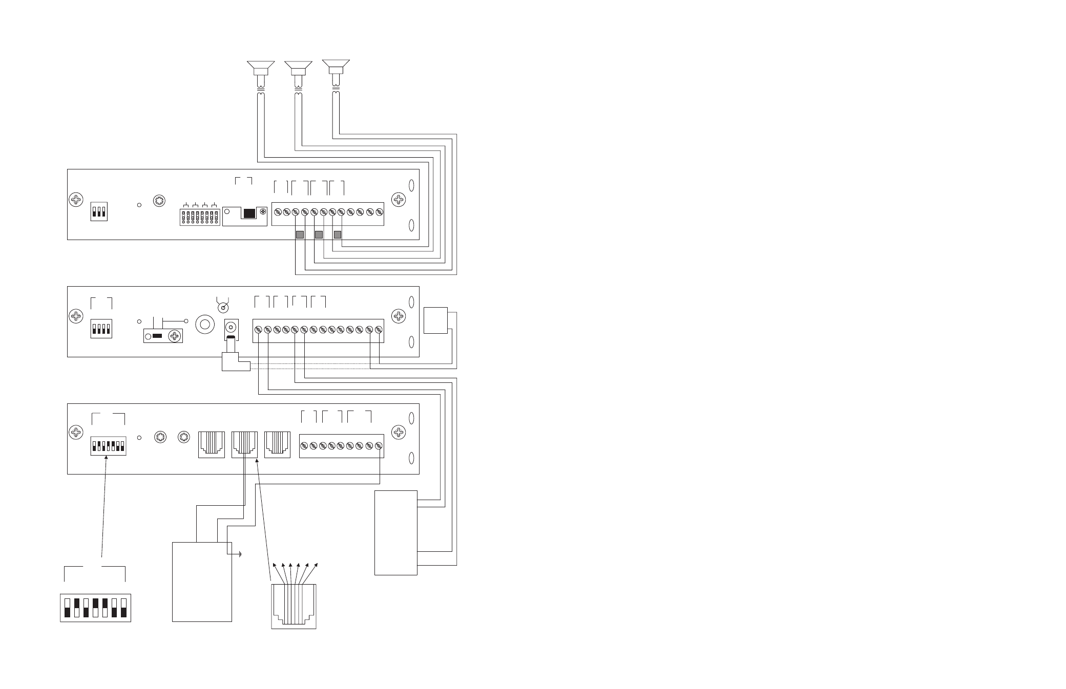
SETUP FOR CONFIGURATION 4: GROUND START TRUNK - 3-ZONE - ONE-WAY PAGING - SINGLE AMPLIFIER - 25/70V AC SPEAKERS