Bogen PCM2000 User Manual
Page 20
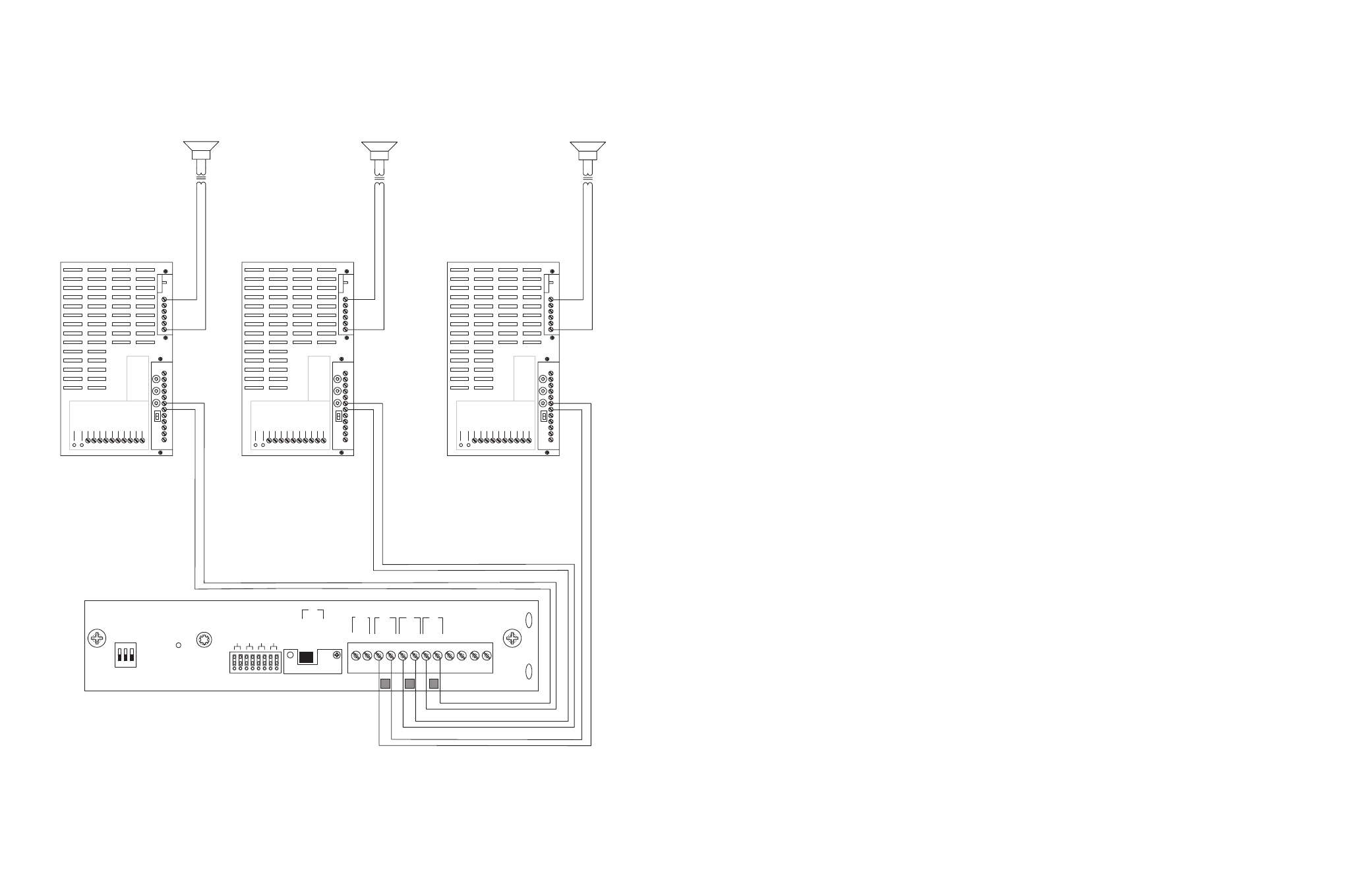
CONFIGURATION 9:
3-ZONE - ONE-WAY PAGING - LOW-POWER SYSTEM - DEDICATED AMPLIFIERS OR SELF-AMPLIFIED SPEAKERS
Low-Power System is a switch-selectable feature that allows the system designer to use dedicated amplifiers or self-amplified speakers on the
zone outputs.The PCMZPM module that is to be used as a low-power module will switch only low-level signals to the zone outputs for use
with dedicated amplifiers or self-amplified speakers. Note that its output switch is set to LO PWR. In this example, three TPU100B amplifiers
are used but amplified speakers can be substituted.
Note: Low-Power Systems do not support two-way paging.
INSTALLATION:
STEP 1: Assembling Modules
•
Follow the same procedure described previously on page 5, step 1.
Note: Do NOT connect the PCMPS2 (power supply) at this point.
STEP 2: Connecting Telephone System Paging Output to the PCMTIM
•
Refer to paging access modes described previously in Step 2 on pages 5 (paging port/contact closure), 7 (paging port/VOX), 9 (loop start
trunk), 11 (ground start trunk), or 13 (station level/Centrex).
STEP 3: Switch Settings
•
Set the TEL-INT-SEL DIP switches on the PCMTIM module to match the paging output access from the telephone system based on the
type of telephone interface used. (See step 3 on page 5 if using Page Port Contact Closure; page 7 for Page Port VOX; page 9 for Loop
Start Trunk; page 11 for Ground Start Trunk; or page 13 for Station Level/Centrex.)
•
Set the SYS-ID switches on the PCMCPU to the OFF position (to the left).
•
Set the TALKBACK switches on the PCMZPM to the OFF position (to the left) for all zones.
•
Set the LO PWR / HI PWR OUTPUT switch on the PCMZPM to the LO PWR position (up).
STEP 4: Connecting the Paging Amplifiers
•
Locate the terminals on the PCMZPM module labeled ZONE A and connect to the TIP and RING terminals of the amplifier(s) for
ZONE A.
•
Follow the same procedure for ZONE B and ZONE C.
STEP 5: Connecting Self-Amplified Speakers
•
Locate the terminals on the amplifiers labeled COM and 25V or 70V AC and connect the speakers related to that particular zone.
STEP 6: Testing Your System
•
Follow the same procedure described previously on page 5, step 7.
20
21
PCM
ZPM
PO
WER
RD COM
+
-
RD A
RD B
ZONE A
ZONE B
ZONE C
OFF ON
T
ALKBA
CK
RT
IN
RD C
LOCAL
BGM
ZONE A
+
-
ZONE B
+
-
ZONE C
LPBGM
V
OLUME
LO PWR
HI PWR
OUTPUT
BGM
OUT IN
PO
WER LED
PEAK LEVEL
APHEX
TREBLE
BASS
V
O
X SENS
RING V
OLUME
MUSIC MUTE
MUSIC V
OLUME
MIC V
OLUME
TEL V
OLUME
ALC
MODEL TPU-100B
100W
A
TT AMPLIFIER
BOGEN
PO
WER LED
PEAK LEVEL
APHEX
TREBLE
BASS
V
O
X SENS
RING V
OLUME
MUSIC MUTE
MUSIC V
OLUME
MIC V
OLUME
TEL V
OLUME
ALC
MODEL TPU-100B
100W
A
TT AMPLIFIER
BOGEN
PO
WER LED
PEAK LEVEL
APHEX
TREBLE
BASS
V
O
X SENS
RING V
OLUME
MUSIC MUTE
MUSIC V
OLUME
MIC V
OLUME
TEL V
OLUME
ALC
MODEL TPU-100B
100W
A
TT AMPLIFIER
BOGEN
ZONE A
ZONE B
ZONE C
GLOBL BGM
ZONE C
ZONE B
ZONE A
SETUP FOR CONFIGURATION 9: 3-ZONE - ONE-WAY PAGING - LOW-POWER SYSTEM - DEDICATED AMPLIFIERS OR SELF-AMPLIFIED SPEAKERS