Pbx st a tion a ccess centrex t r, Bogen, Bogen p a ging amplifier – Bogen PCM2000 User Manual
Page 11
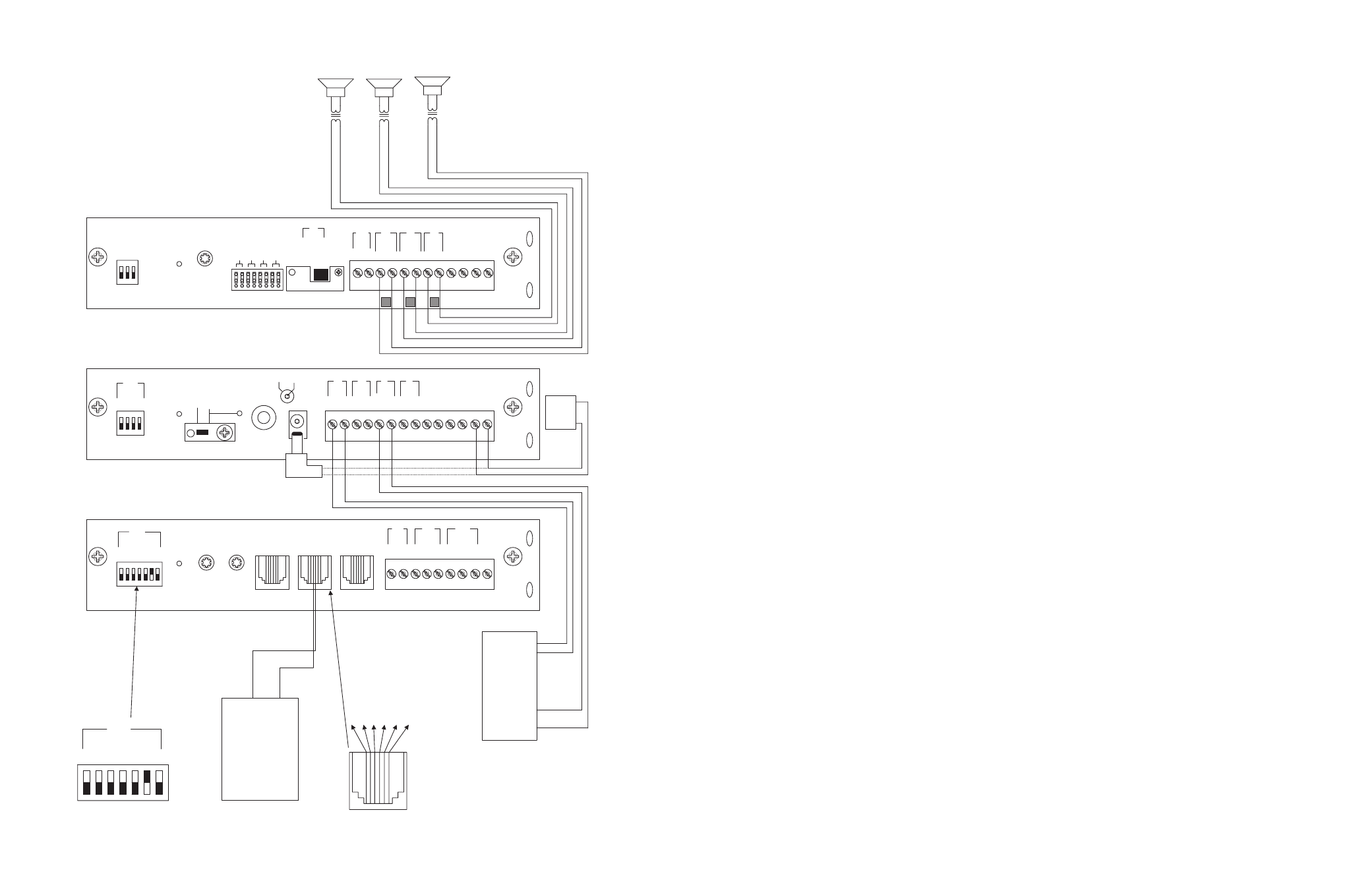
CONFIGURATION 13:
EMERGENCY VOICE ANNOUNCEMENT OVERRIDE
Voice Announcement Override is a non-programmable feature that lets the caller take priority over all paging functions and make a system-
wide emergency voice announcement page to all speakers. In addition to the PCM modules, this option requires a ProHold (digital announc-
er) and a normally open momentary switch supplied by the user.
The Override feature includes a quad beep pre-announce tone which can be enabled or inhibited through programming.
INSTALLATION:
STEP 1: Assembling Modules and Connecting the Amplifier
•
Refer to step 1 on pages 5 and 17.
STEP 2: Connecting the Paging Amplifier
•
Follow the same procedure described previously on page 5 or 17, step 5.
STEP 3: Connecting Optional Equipment
•
Attach a 6-pin RJ11 modular jack to the wall next to the PCM2000 unit.
•
Connect the audio output from the ProHold labeled Line 600 using the supplied RCA cable to the RJ11 modular jack terminals Y (yel-
low) and BK (black).
•
Using the supplied stereo mini-plug, connect it to the TRIG input connector of the ProHold Digital Announcer. At the end of this cable,
you will see 3 bare wires labeled TIP, BARREL and RING.
•
Connect the TIP wire to one of the terminals on the normally open connections of the customer-supplied switch and the other switch
terminal to the RJ11 modular jack terminal BL (blue).
•
Connect the BARREL wire to the RJ11 modular jack terminal BL (blue). At this point you should have two wires connected to the BL
(blue) terminal.
•
Connect the RING wire to the RJ11 modular jack terminal W (white).
•
Connect a 6-pin RJ11 modular cable between the RJ11 modular jack and the Override RJ11 input on the PCMTIM module.
STEP 4: Switch and Control Settings
•
Set the TEL-INT-SEL DIP switches on the PCMTIM module to match the paging output access from the telephone system based on the
type of telephone interface used. (See step 3 on page 5 if using Page Port Contact Closure; page 7 for Page Port VOX; page 9 for Loop
Start Trunk; page 11 for Ground Start Trunk; or page 13 for Station Level/Centrex.)
STEP 5: Testing Your System
•
Connect the power supply PCMPS2 to the PCMCPU module to either the power jack 12V DC input or wire it to the 12V DC screw
terminals, observing polarity.
•
Connect the Bogen amplifier to the AC power outlet (120V AC 60Hz).
•
Set the volume on your Bogen amplifier to a half turn.
•
Insert a pre-recorded normal bias audio tape into the ProHold cassette compartment.
•
Once the ProHold announcer has downloaded the audio and the LOAD light goes "OFF", press the normally open customer supplied
switch once and listen for the all-call announcement.
12
29
PCM
TIM
PO
WER
T
ONE
V
OLUME
BGM SRC
V
OLUME
GND ST
IN
RT
BGM
SRC
NIGHT
RING
TEL
LINE
O
VER
RIDE
NC
COM
NO
NC
COM
NO
RL
Y
ONE
RL
Y
TW
O
S1
S2
S3
S4
S5
S6
S7
TEL
INT
SEL
0 1
PO
WER
- 1.5A
OUT
RT
GND
AU
X
GND
S1
S2
S3
S4
0 1
SYS
ID
RU
N
PR
OGRAM
DA
T
A
LINK
12 VDC
1.5A
-
IN
RT
RT
IN
RT
IN
EM/SC
+ 12VDC
BOGEN
PA
LPBGM
PA
HPBGM
+
PO
WER
RD COM
+
-
RD A
RD B
ZONE A
ZONE B
ZONE C
OFF ON
T
ALKBA
CK
RT
IN
RD C
LOCAL
BGM
ZONE A
+
-
ZONE B
+
-
ZONE C
LPBGM
V
OLUME
LO PWR
HI PWR
OUTPUT
BGM
OUT IN
PCM
ZPM
PCM
CPU
PBX
ST
A
TION
A
CCESS
CENTREX
T
R
1 - Not used
2 - Not used
3 - Ring (Negativ
e)
4 -
Tip (P
ositiv
e)
5 - Not used
6 - Not used
+
-
PCM PS2
RT
70V
COM
BOGEN P
A
GING
AMPLIFIER
S1
S2
S3
S4
S5
S6
S7
TEL
INT
SEL
0 1
ZONE A
ZONE B
ZONE C
GLOBL BGM
ZONE C
ZONE B
ZONE A
SETUP FOR CONFIGURATION 5: STATION LEVEL/CENTREX - 3-ZONE - ONE-WAY PAGING - SINGLE AMPLIFIER - 25/70V AC SPEAKERS