Sa tellite assembl y #1 master assembl y, Bogen, Bogen p a ging amplifier – Bogen PCM2000 User Manual
Page 22
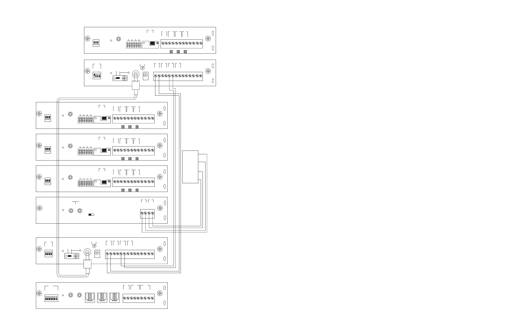
CONFIGURATION 10:
6 ZONES - ONE-WAY PAGING - MIXED HIGH- AND LOW-POWER ZONES -
25/70V AC OR SELF-AMPLIFIED SPEAKERS
High- and Low-Power Mixed System is a non-programmable feature that lets the system designer use a dedicated amplifier or self-amplified
speaker per zone and at the same time use a centralized amplifier for zones requiring less than 250 watts of power*.The PCMZPM module
to be used as a low-power module must have all three zones with dedicated amplifiers or self-amplified speakers and have its output switch
set to Low-Power.The other PCMZPM module will be used as a high-power module and its output switch must be set to High-Power. In this
example, three TPU100B amplifiers are used on the second PCMZPM low-power module.
Note: Low-Power Systems do not support two-way paging.
INSTALLATION:
STEP 1: Assembling Modules
•
Follow the same procedure described previously on page 5, step 1.
Note: Do NOT connect PCMPS2 (power supply) at this point.
STEP 2: Connecting Telephone System Paging Output to the PCMTIM
•
Refer to paging access modes described previously in Step 2 on pages 5 (paging port/contact closure), 7 (paging port/VOX), 9 (loop start
trunk), 11 (ground start trunk), or 13 (station level/Centrex).
STEP 3: Switch and Control Settings
•
Set the TEL-INT-SEL DIP switches on the PCMTIM module to match the paging output access from the telephone system based on the
type of telephone interface used. (See step 3 on page 5 if using Page Port Contact Closure; page 7 for Page Port VOX; page 9 for Loop
Start Trunk; page 11 for Ground Start Trunk; or page 13 for Station Level/Centrex.)
•
Set the SYS ID switches on the PCMCPU module to the OFF position (to the left).
•
Set the TALK BACK switches on the PCMZPM module to the OFF position (to the left) for all zones.
•
Set the LO PWR / HI PWR OUTPUT switch on the first PCMZPM High-Power module to the HI PWR OUTPUT position (down).
•
Set the LO PWR / HI PWR OUTPUT switch on the second PCMZPM Low-Power module to the LO PWR OUTPUT position (up).
STEP 4: Connecting Amplifiers
•
Locate the terminals on the PCMCPU module labeled PA IN/RT and wire it to the TIP and RING (T & R) input on the amplifier.
•
Locate the terminals on the PCMCPU module labeled PA OUT/RT and wire it to the COMMON and either 25 or 70V AC output on
the amplifier.
•
Locate the terminals on the second PCMZPM module Low-Power module labeled ZONE A and connect the amplifier to the TIP and
RING terminals. Follow the same procedure for ZONE B and ZONE C.
STEP 5: Connecting 25/70V AC Speakers
•
Follow the same procedure described previously on page 5, step 6.
STEP 6: Testing Your System
•
Connect the power supply PCMPS2 to the PCMCPU module to either the power jack 12V DC input or wire it to the 12V DC screw
terminals observing polarity.
•
Connect the Bogen amplifiers to the AC power outlet (120 V AC 60Hz).
•
Set the volume on your Bogen amplifiers to a 1/2 turn.
•
Access the Paging from the telephone system and listen (on the handset) for the confirmation tone (double beep).
• Dial
01 to access ZONE ONE and listen (on the handset and also to the speakers) for a pre-announce tone (single beep) followed by
your page (audio).
•
Follow the same steps for ZONES TWO (02) through SIX (06).
•
Set the Bogen amplifiers to the desired volume level.
* Older PCM systems only have a 150W capacity.
18
23
PCM
TIM
PO
WER
T
ONE
V
OLUME
BGM SRC
V
OLUME
GND ST
IN
RT
BGM
SRC
NIGHT
RING
TEL
LINE
O
VER
RIDE
NC
COM
NO
NC
COM
NO
RL
Y
ONE
RL
Y
TW
O
S1
S2
S3
S4
S5
S6
S7
TEL
INT
SEL
0 1
PO
WER
- 1.5
A
OUT
RT
GND
AU
X
GND
S1
S2
S3
S4
0 1
SYS
ID
RU
N
PR
OGRAM
DA
T
A
LINK
12 VDC
1.5 A
-
IN
RT
RT
IN
RT
IN
EM/SC
+ 12VDC
BOGEN
PA
LPBGM
PA
HPBGM
+
PO
WER
RD COM
+
-
RD A
RD B
ZONE A
ZONE B
ZONE C
OFF ON
T
ALKBA
CK
RT
IN
RD C
LOCAL
BGM
ZONE A
+
-
ZONE B
+
-
ZONE C
LPBGM
V
OLUME
LO PWR
HI PWR
OUTPUT
BGM
OUT IN
PCM
ZPM
PCM
CPU
70V
COM
T
R
BOGEN P
A
GING
AMPLIFIER
PO
WER
RD COM
+
-
RD A
RD B
ZONE A
ZONE B
ZONE C
OFF ON
T
ALKBA
CK
RT
IN
RD C
LOCAL
BGM
ZONE A
+
-
ZONE B
+
-
ZONE C
LPBGM
V
OLUME
LO PWR
HI PWR
BGM
OUT IN
PO
WER
RD COM
+
-
RD A
RD B
ZONE A
ZONE B
ZONE C
OFF ON
T
ALKBA
CK
RT
IN
RD C
LOCAL
BGM
ZONE A
+
-
ZONE B
+
-
ZONE C
LPBGM
V
OLUME
LO PWR
HI PWR
OUTPUT
BGM
OUT IN
PCM
ZPM
PO
WER
- 1.5 mA
OUT
RT
GND
AU
X
GND
S1
S2
S3
S4
0 1
SYS
ID
RU
N
PR
OGRAM
DA
T
A
LINK
12 VDC
1.5 A
-
IN
RT
RT
IN
RT
IN
EM/SC
+ 12VDC
BOGEN
PA
LPBGM
PA
HPBGM
+
PCM
CPU
PO
WER
RD COM
+
-
RD A
RD B
ZONE A
ZONE B
ZONE C
OFF ON
T
ALKBA
CK
RT
IN
RD C
LOCAL
BGM
ZONE A
+
-
ZONE B
+
-
ZONE C
LPBGM
V
OLUME
LO PWR
HI PWR
OUTPUT
BGM
OUT IN
PCM
ZPM
SA
TELLITE ASSEMBL
Y #1
MASTER ASSEMBL
Y
PCM
ZPM
PCM
TBM
PO
WER
V
OLUME
T
ALKB
A
CK
DELA
Y
OUT
RT
IN
RT
PA
PA
NOISE
REDUCTION
ON
OFF
ZONE A
ZONE B
ZONE C
GLOBL BGM
ZONE A
ZONE B
ZONE C
GLOBL BGM
ZONE A
ZONE B
ZONE C
GLOBL BGM
ZONE A
ZONE B
ZONE C
GLOBL BGM
OUTPUT
SETUP FOR CONFIGURATION 8:TWO-WAY TALK BACK EXTENDED PAGING SYSTEM