Bogen PCM2000 User Manual
Page 15
CONFIGURATION 11:
MICROPHONE OVERRIDE
Microphone Override is a feature that lets the system designer take priority over all paging functions and make a system-wide page to all
speakers.
In addition to the PCM modules, setup requires a Bogen VAR1 (voice-activated relay), PRS40C (12V DC power supply) and an MBS1000 or
DDU250 (desktop microphone).
The Override feature includes a quad beep pre-announce tone which can be enabled or inhibited.
INSTALLATION:
STEP 1: Assembling Modules and Connecting the Amplifier
•
Refer to step 1 on pages 5 and 17.
STEP 2: Connecting the Paging Amplifier
•
Follow the same procedure described previously on page 5 or 17, step 5.
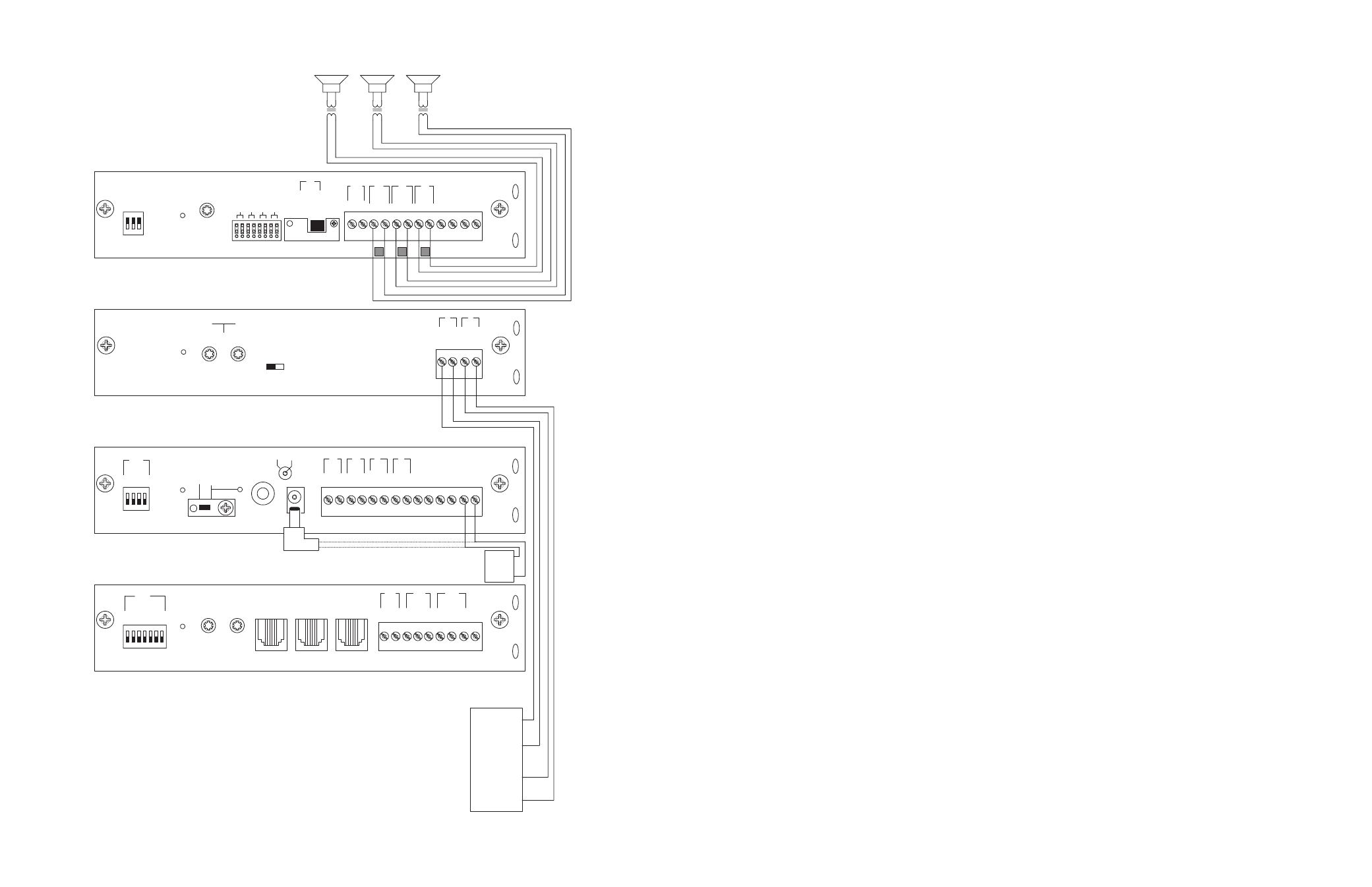
STEP 3: Connecting Optional Equipment
•
Attach a 6-pin RJ11 modular jack to the wall next to the PCM2000 unit.
•
Connect the first audio output terminal from the top of the VAR1 (right screw terminals) to the RJ11 modular jack terminal Y (yellow).
Connect the second audio output terminal from the top of the VAR1 to the N.O. contact of the VAR1.
•
Connect the fifth screw terminal from the top of the VAR1 (see drawing) to the RJ11 modular jack terminal BK (black).
•
Connect the relay terminals (normally open contacts) from the VAR1 (two bottom right screw terminals) to the RJ11 modular jack ter-
minals W (white) and BL (blue).
•
Connect the MBS1000 or DDU250 microphone leads to the VAR1 (left screw terminals): red to third screw, black to fifth screw, and
shield to fourth screw.
•
Do not use the white and green wires from the MBS1000 or DDU250 unless you want to use them instead of the normally open con-
tacts on the VAR1.
•
Connect a 6-pin RJ11 modular cable between the RJ11 modular jack (previously attached to the wall next to the PCM2000) and the
Override RJ11 input on the PCMTIM module.
•
Connect the PRS40C power supply to the VAR1 (two top left screw terminals) observing polarity or use the mini-plug and connect it
into the mini-jack at the bottom.
STEP 4: Switch and Control Settings
•
Set the TEL-INT-SEL DIP switches on the PCMTIM module to match the paging output access from the telephone system based on the
type of telephone interface used. (See step 3 on page 5 if using Page Port Contact Closure; page 7 for Page Port VOX; page 9 for Loop
Start Trunk; page 11 for Ground Start Trunk; or page 13 for Station Level/Centrex.)
•
Set the Line/MIC switch on the VAR1 to the MIC position.
•
Set the Mic volume control on the VAR1 at 50%.
STEP 5: Testing Your System
•
Connect the power supply PCMPS2 to the PCMCPU module to either the power jack 12V DC input or wire it to the 12V DC screw
terminals observing polarity.
•
Connect the Bogen amplifier to the AC power outlet (120V AC 60Hz).
•
Set the volume on your Bogen amplifier a half turn.
•
Access the paging from the telephone system and listen (on the handset) for the confirmation tone (double beep).
• Dial
01 to access ZONE ONE and listen (on the handset and also to the speakers) for a pre-announce tone (single beep) followed by
your page (audio).
•
Follow the same steps for ZONES TWO (02) and THREE (03).
•
Access the emergency override by pressing the talk bar on the MBS1000 or sliding the DDU250 switch.
•
You should hear a quad beep pre-announce tone followed by your all-call/emergency page.
• Adjust
the
VAR1 and PCM2000 controls for optimal operation.
NOTE: You will not be able to access individual zones using the Override feature, it is for All-Call Emergency only to all
zones.
16
25
PCM
TIM
PO
WER
T
ONE
V
OLUME
BGM SRC
V
OLUME
GND ST
IN
RT
BGM
SRC
NIGHT
RING
TEL
LINE
O
VER
RIDE
NC
COM
NO
NC
COM
NO
RL
Y
ONE
RL
Y
TW
O
S1
S2
S3
S4
S5
S6
S7
TEL
INT
SEL
0 1
PO
WER
- 1.5
A
OUT
RT
GND
AU
X
GND
S1
S2
S3
S4
0 1
SYS
ID
RU
N
PR
OGRAM
DA
T
A
LINK
12 VDC
1.5A
-
IN
RT
RT
IN
RT
IN
EM/SC
+ 12VDC
BOGEN
PA
LPBGM
PA
HPBGM
+
PO
WER
RD COM
+
-
RD A
RD B
ZONE A
ZONE B
ZONE C
OFF ON
T
ALKBA
CK
RT
IN
RD C
LOCAL
BGM
ZONE A
+
-
ZONE B
+
-
ZONE C
LPBGM
V
OLUME
LO PWR
HI PWR
OUTPUT
BGM
OUT IN
PCM
ZPM
PCM
CPU
+
-
PCM PS2
R
T
70V
COM
BOGEN P
A
GING
AMPLIFIER
PCM
TBM
PO
WER
V
OLUME
T
ALKB
A
CK
DELA
Y
OUT
RT
IN
RT
PA
PA
NOISE
REDUCTION
ON
OFF
ZONE A
ZONE B
ZONE C
GLOBL BGM
ZONE C
ZONE B
ZONE A
SETUP FOR CONFIGURATION 7:TWO-WAY TALK BACK PAGING SYSTEM