Music source bogen tp30d – Bogen PCM2000 User Manual
Page 8
CONFIGURATION 3:
LOOP START TRUNK - 3-ZONE - ONE-WAY PAGING - SINGLE AMPLIFIER - 25/70V AC SPEAKERS
In this configuration, the PCM unit supplies a 48V talk battery and loop current detection from pins 3 & 4 of the TEL LINE jack on the
PCMTIM module to the loop start trunk in the telephone system.There are two modes of operation for loop start trunk.
(1) When the unit detects a loop resistance between TIP and RING, it activates.When the loop opens, the page ends. Pins 1, 2, 5 & 6 are not
used in this configuration. Note: Default and VOX timers are not used in this mode.
(2) The unit will operate as in mode one, except it will also provide a one-second hook flash after the expiration of the VOX and/or Default
timers. Operation in this mode will enable the unit to automatically disconnect itself from the loop start trunk of the PBX.This will prevent
the paging system from being locked up indefinitely in the event a telephone is accidentally left off hook after a page has been completed.The
feature codes are 014 to inhibit and 015 to enable this feature.The default feature code is 014 (OFF).
The required setup includes PCMTIM - PCMCPU - PCMZPM - PCMPS2. Modules must be assembled, from left to right, in this order.
INSTALLATION:
STEP 1: Assembling Modules PCMTIM to PCMCPU and to PCMZPM
•
Follow the same procedure described previously on page 5, step 1.
Note: Do NOT connect the PCMPS2 (power supply) at this point.
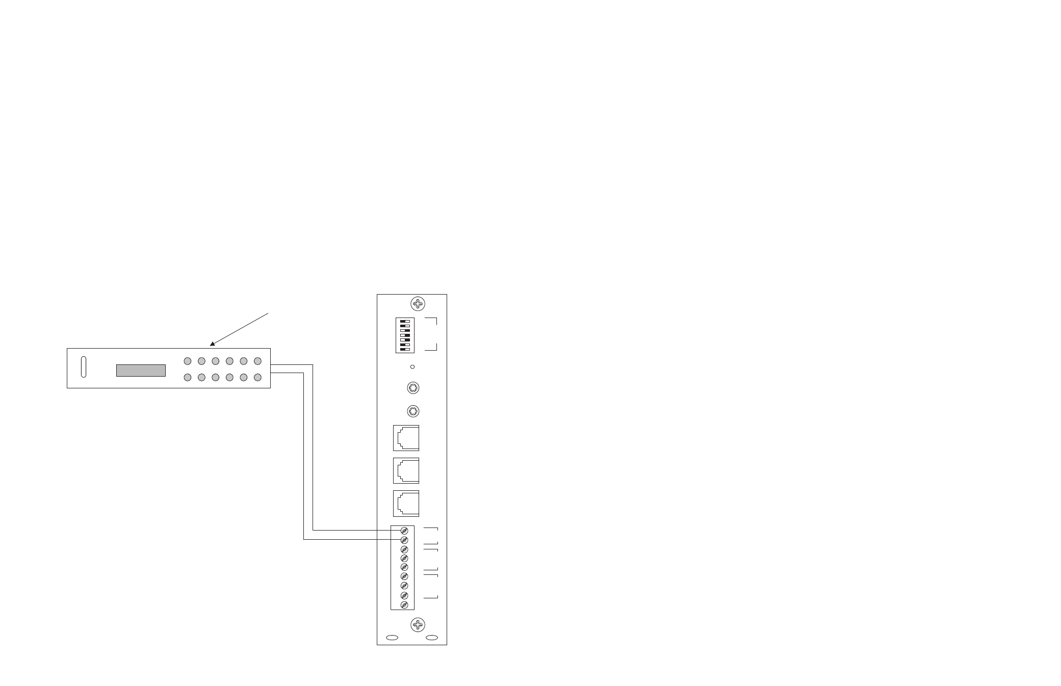
STEP 2: Connecting Loop Start Trunk from the Telephone System to the PCMTIM Module
•
Take the loop start trunk pair from the telephone system and wire it to the RJ11 TEL-LINE jack in the PCMTIM module to pins 3 and 4
(red and green).
•
Use a 4 or 6-pin modular cord to connect the RJ11 to the TEL-LINE input on the PCMTIM module.
STEP 3: Switch Settings
•
Set the TEL-INT-SEL DIP switches on the PCMTIM module for Loop Start Trunk configuration: switches 3, 4 & 5 ON (to the right) and
switches 1, 2, 6 & 7 OFF (to the left).
•
Set the SYS-ID DIP switches on the PCMCPU module to the OFF position (to the left).
•
Set the RUN-PROGRAM switch on the PCMCPU module to the RUN mode (up).
•
Set the Talk Back DIP switches on the PCMZPM module to the OFF position (to the left) for all zones.
•
Set the OUTPUT switch on the PCMZPM module to the HI-PWR position (down).
STEP 4: Testing your System
•
Connect power supply PCMPS2 to the PCMCPU module to either the power jack 12V DC input or wire it to the 12V DC screw ter-
minals observing polarity.
•
Power LEDs should be lit on each module.
•
Access the Loop Start Trunk from the phone system and verify access tones (double beep).
•
At this point, the system should be functioning properly.
•
Disconnect Power Supply.
STEP 5: Connecting the Paging Amplifier
•
Follow the same procedure described previously on page 5, step 5.
STEP 6: Connecting 25/70V AC Speakers
•
Follow the same procedure described previously on page 5, step 6.
STEP 7: Testing your System
•
Connect the power supply PCMPS2 to the PCMCPU module to either the power jack 12V DC input or wire it to the 12V DC screw
terminals observing polarity.
•
Connect the Bogen amplifier to the AC power outlet (120V AC 60Hz).
•
Set the volume on your Bogen amplifier to a 1/2 turn.
•
Access the Loop Start Trunk from the telephone system and listen (on the handset) for the confirmation tone (double beep).
• Dial
01 to access ZONE ONE and listen (on the handset and also to the speakers) for a pre-announce tone (single beep) followed by
your page (audio)
•
Follow the same steps for ZONES TWO (02) and THREE (03).
•
Set the Bogen amplifier to the desired volume level.
32
9
PCM
TIM
POWER
TONE VOLUME
BGM SRC
VOLUME
GND ST
IN
RT
BGM
SRC
NIGHT RING
TEL
LINE
OVER RIDE
NC
COM
NO
NC
COM
NO
RLY ONE
RLY TWO
S1
S2
S3
S4
S5
S6
S7
TEL
INT
SEL
0 1
BOGEN
TP30D DIGITAL TUNER
Music Source
Bogen TP30D
UP BAND MSCAN M1 M2 M3
DOWN MONO ME M4 M5 M6
POWER
CONFIGURATION 15:
SINGLE AMPLIFIER BACKGROUND MUSIC LINE-LEVEL SIGNAL
Single amplifier BGM operation is a programmable feature that lets the PCM2000 use the paging amplifier to provide high-power BGM to the
25/70V AC speakers when the paging system is idle.
INSTALLATION:
STEP 1: Connecting Telephone System Paging Output to the PCMTIM
•
Refer to paging access modes described previously in Step 2 on pages 5 (paging port/contact closure), 7 (paging port/VOX), 9 (loop start
trunk), 11 (ground start trunk), or 13 (station level/Centrex).
STEP 2: Connecting the BGM Source
•
Connect the BGM source output to the PCMTIM module terminals labeled BGM SOURCE IN/RT.
STEP 3: PCMCPU Switch Settings
•
Remove the switch lock on the PCMCPU module and place the PROGRAM/RUN switch to the PROGRAM position (down), the green
LED will illuminate.
STEP 4:Testing the System
•
Access the PCM2000 system (either use a single 2500-series line telephone or butt set or dial the paging access number from the tele-
phone system).You will hear 3 beep tones indicating access to the programming mode.
•
Dial 019 follow by the ( # ) key.You will hear a short double beep if the programming was accepted and stored in the system.
STEP 5: Prepare System for Operation
•
Hang up the programming phone and then place the PROGRAM/RUN switch in the RUN position.The green LED will go out. Replace
the switch lock.