Bogen – Bogen PCM2000 User Manual
Page 21
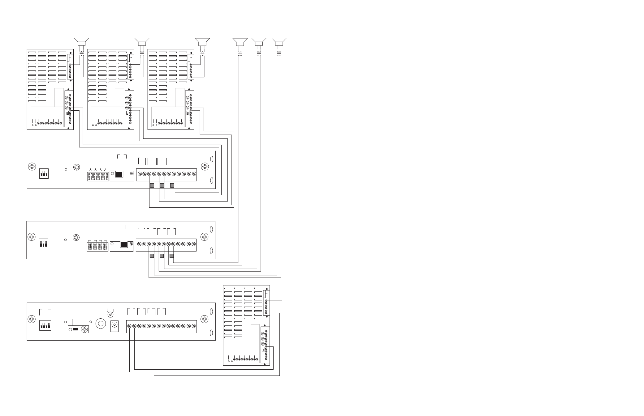
CONFIGURATION 8:
TWO-WAY TALK BACK EXTENDED PAGING SYSTEM
This configuration is essentially the same as the two-way paging system described previously on page 17.The main difference is the addition
of a satellite assembly.
The required setup includes: PCMTIM - 2 PCMCPU - PCMTBM - 4 PCMZPM - 2 PCMPS2
Note:
Talk Back is only available in High-Power Zones with 25/70V AC speakers.
The paging access output from the telephone system must support two-way communications.
INSTALLATION:
STEP 1: Assembling Master Modules PCMTIM to PCMCPU to PCMTBM and to PCMZPM
•
Follow the same procedure described previously on page 17, step 1.
Note: Do NOT connect the PCMPS2 (power supply) at this point.
STEP 2: Assembling Satellite Modules PCMCPU to PCMZPM
•
Follow the same procedure described previously on page 15, step 2.
STEP 3: Switch Settings
•
Set the TEL-INT-SEL DIP switches on the PCMTIM module to match the paging output access from the telephone system based on the
type of telephone interface used. (See step 3 on page 5 if using Page Port Contact Closure; page 7 for Page Port VOX; page 9 for Loop
Start Trunk; page 11 for Ground Start Trunk; or page 13 for Station Level/Centrex.)
•
Set the SYS-ID DIP switches on the master PCMCPU module to the OFF position (to the left).
•
Set the SYS-ID DIP switches on the first satellite PCMCPU module to the following configuration: switch 1 to the ON position (to the
right), switches 2, 3, & 4 to the OFF position (to the left). See additional SYS-ID settings on page 38.
•
Set the RUN-PROGRAM switch on each PCMCPU to the RUN mode (up).
•
Set the TALK BACK switches on the PCMZPM modules to the ON position (to the right) for all zones.
•
Set the OUTPUT switch on each PCMZPM module to the HI-PWR position (down).
STEP 4: Testing your System
•
Connect one PCMPS2 power supply to each PCMCPU module to either the power jack 12V DC input or wire it to the 12V DC screw
terminals, observing polarity.
•
At this point all the power LEDs should be lit on each module.
•
Access the paging from the phone system and verify access tones (double beep).
•
At this point, the system should be functioning properly.
•
Disconnect Power Supply.
STEP 5: Connecting the Paging Amplifier
•
Locate the terminals on the PCMTBM module labeled PA OUT/RT and wire to the COMMON and either 25 or 70V output on the
Bogen paging amplifier (either TPU-Series, GS-Series or Classic Series).
•
Locate the terminals on the PCMTBM module labeled PA IN/RT and wire to the TIP and RING input on the Bogen paging amplifier.
STEP 6: Connecting 25/70V AC Speakers
•
Follow the same procedure described previously on page 5, step 6.
STEP 7: Testing your System
•
Connect a PCMPS2 power supply to each PCMCPU module to either the power jack 12V DC input or wire it to the 12V DC screw
terminals observing polarity.
•
Connect the Bogen amplifier to the AC power outlet (120V AC 60Hz).
•
Set the volume on your Bogen amplifier to a 1/2 turn.
•
Access the paging from the telephone system and listen (on the handset) for the confirmation tone (double beep).
• Dial
01 to access ZONE ONE and listen (on the handset and also to the speakers) for a pre-announce tone (single beep).At this point,
you should be able to hear audio from the location where the speaker for ZONE ONE is installed.
•
The volume and delay controls on the PCMTBM module, control the audio back into the handset.Adjust these controls for best opera-
tion.
•
Set the Bogen amplifier to the desired volume level.
22
19
PCM
ZPM
PO
WER
RD COM
+
-
RD A
RD B
ZONE A
ZONE B
ZONE C
OFF ON
T
ALKBA
CK
RT
IN
RD C
LOCAL
BGM
ZONE A
+
-
ZONE B
+
-
ZONE C
LPBGM
V
OLUME
LO PWR
HI PWR
OUTPUT
BGM
OUT IN
PO
WER LED
PEAK LEVEL
APHEX
TREBLE
BASS
V
O
X SENS
RING V
OLUME
MUSIC MUTE
MUSIC
V
OLUME
MIC V
OLUME
TEL V
OLUME
ALC
MODEL TPU-100B
100W
A
TT AMPLIFIER
BOGEN
PO
WER LED
PEAK LEVEL
APHEX
TREBLE
BASS
V
O
X SENS
RING V
OLUME
MUSIC MUTE
MUSIC
V
OLUME
MIC V
OLUME
TEL V
OLUME
ALC
MODEL TPU-100B
100W
A
TT AMPLIFIER
BOGEN
PO
WER LED
PEAK
LEVEL
APHEX
TREBLE
BASS
V
O
X SENS
RING V
OLUME
MUSIC MUTE
MUSIC
V
OLUME
MIC V
OLUME
TEL V
OLUME
ALC
MODEL TPU-100B
100W
A
TT AMPLIFIER
BOGEN
PCM
ZPM
PO
WER
RD COM
+
-
RD A
RD B
ZONE A
ZONE B
ZONE C
OFF ON
T
ALKBA
CK
RT
IN
RD C
LOCAL
BGM
ZONE A
+
-
ZONE B
+
-
ZONE C
LPBGM
V
OLUME
LO PWR
HI PWR
OUTPUT
BGM
OUT IN
PO
WER
- 1.5
A
OUT
RT
GND
AU
X
GND
S1
S2
S3
S4
0 1
SYS
ID
RU
N
PR
OGRAM
DA
T
A
LINK
12 VDC
1.5 A
-
IN
RT
RT
IN
RT
IN
EM/SC
+ 12VDC
BOGEN
PA
LPBGM
PA
HPBGM
+
PCM
CPU
PO
WER LED
PEAK LEVEL
APHEX
TREBLE
BASS
V
O
X SENS
RING V
OLUME
MUSIC MUTE
MUSIC
V
OLUME
MIC V
OLUME
TEL V
OLUME
ALC
MODEL TPU-100B
100W
A
TT AMPLIFIER
BOGEN
ZONE A
ZONE B
ZONE C
GLOBL BGM
ZONE A
ZONE B
ZONE C
GLOBL BGM
ZONE C
ZONE B
ZONE A
ZONE A
ZONE B
ZONE C
SETUP FOR CONFIGURATION 10: 6 ZONES - ONE-WAY PAGING - MIXED HIGH- AND LOW-POWER ZONES -
25/70V AC OR SELF-AMPLIFIED SPEAKERS