Pbx p a ging por t t r – Bogen PCM2000 User Manual
Page 3
Time Trigger 6
Zone Group
*86
Zone Numbers
No Zones
Inhibit
1
60
Inhibit
Enable
1
61
HHMM
(See Note 3 - below)
2-Second Tone
1
62
3-Second Tone
1
63
3-Second Tone
4-Second Tone
1
64
5-Second Tone
1
65
6-Second Tone
1
66
7-Second Tone
1
67
8-Second Tone
1
68
Chime
1
69
Time Trigger 7
Zone Group
*87
Zone Numbers
No Zones
Inhibit
1
70
Inhibit
Enable
1
71
HHMM
(See Note 3 - below)
2-Second Tone
1
72
3-Second Tone
1
73
3-Second Tone
4-Second Tone
1
74
5-Second Tone
1
75
6-Second Tone
1
76
7-Second Tone
1
77
8-Second Tone
1
78
Chime
1
79
Time Trigger 8
Zone Group
*88
Zone Numbers
No Zones
Inhibit
1
80
Inhibit
Enable
1
81
HHMM
(See Note 3 - below)
2-Second Tone
1
82
3-Second Tone
1
83
3-Second Tone
4-Second Tone
1
84
5-Second Tone
1
85
6-Second Tone
1
86
7-Second Tone
1
87
8-Second Tone
1
88
Chime
1
89
Reset Default
999
Setup Tone (in Program Mode Only)
Turn On
000
Turn Off
Hang Up
Notes to Feature Codes
Note 1- These 2 digits represent time in 10s of seconds, i.e., "01" = 10 seconds, "02" = 20 seconds, "03" = 30 seconds, etc. Entering "00" will
inhibit timer operation
Note 2 - This single-digit indicates VOX delay time in seconds, i.e., "1" = 1 second, "2" = 2 seconds, etc. Entering "0" will inhibit VOX timer
operation.
Note 3 - Entering the Feature Code without additional time data will enable feature using previously programmed time data.
4
37
PCM
TIM
PO
WER
T
ONE
V
OLUME
BGM SRC
V
OLUME
GND ST
IN
RT
BGM
SRC
NIGHT
RING
TEL
LINE
O
VER
RIDE
NC
COM
NO
NC
COM
NO
RL
Y
ONE
RL
Y
TW
O
S1
S2
S3
S4
S5
S6
S7
TEL
INT
SEL
0 1
PO
WER
- 1.5A
OUT
RT
GND
AU
X
GND
S1
S2
S3
S4
0 1
SYS
ID
RU
N
PR
OGRAM
DA
T
A
LINK
12 VDC
1.5A
-
IN
RT
RT
IN
RT
IN
EM/SC
+ 12VDC
BOGEN
PA
LPBGM
PA
HPBGM
+
PO
WER
RD COM
+
-
RD A
RD B
ZONE A
ZONE B
ZONE C
OFF ON
T
ALKBA
CK
RT
IN
RD C
LOCAL
BGM
ZONE A
+
-
ZONE B
+
-
ZONE C
LPBGM
V
OLUME
LO PWR
HI PWR
OUTPUT
BGM
OUT IN
PCM
ZPM
PCM
CPU
PBX
P
A
GING
POR
T
T
R
1 - Not used
2 - Contact Closure
3 - Dr
y audio (R)
4 - Dr
y audio (T)
5 - Contact Closure
6 - Not used
+
-
PCM PS2
RT
70V
COM
BOGEN P
A
GING
AMPLIFIER
S1
S2
S3
S4
S5
S6
S7
TEL
INT
SEL
0 1
CONT
A
CT
CLOSURE
ZONE A
ZONE B
ZONE C
GLOBL BGM
ZONE C
ZONE B
ZONE A
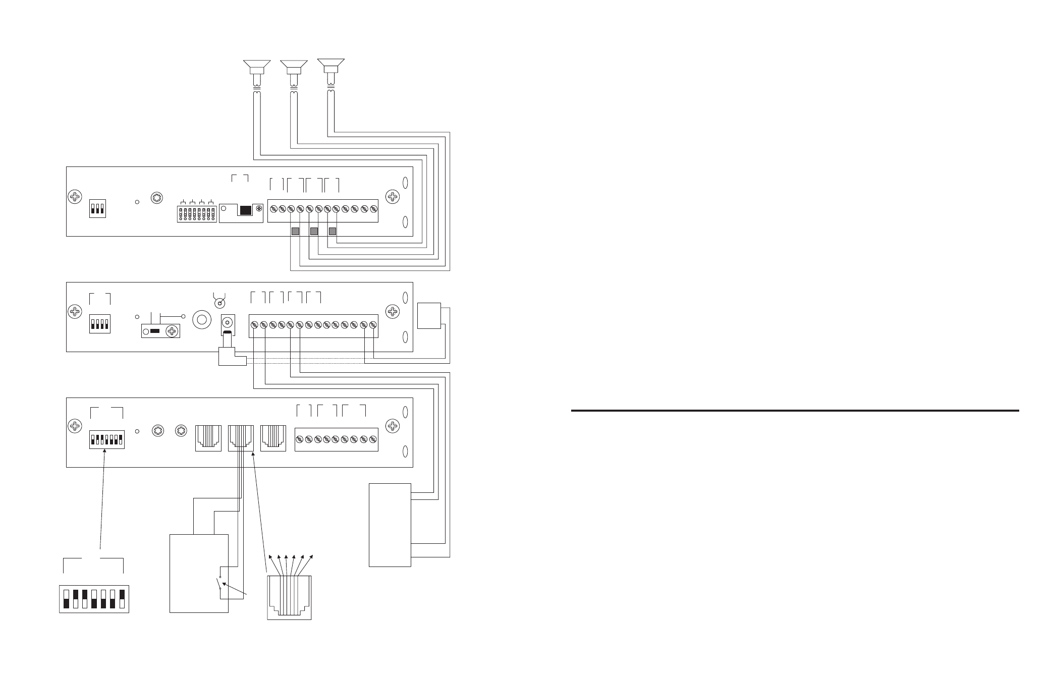
SECTION I: APPLICATION CONFIGURATIONS
SETUP FOR CONFIGURATION 1: PAGE PORT CONTACT CLOSURE - 3-ZONE - ONE-WAY PAGING - SINGLE AMPLIFIER - 25/70V AC SPEAKERS