GeoDesy FSO GD series User Manual
Page 57
com
http://www.geodesy-fso.com
57
GeoDesy Kft.
Telefon: 06-1-481-2050
H-1116 Budapest, Kondorfa str. 6-8.
Fax.:
06-1-481-2049
E-mail:
info@geodesy-fso.
Set the beam size
You can set the beam sizes of each transmitter separately. So do not switch on
more than one transmitter in the same time!
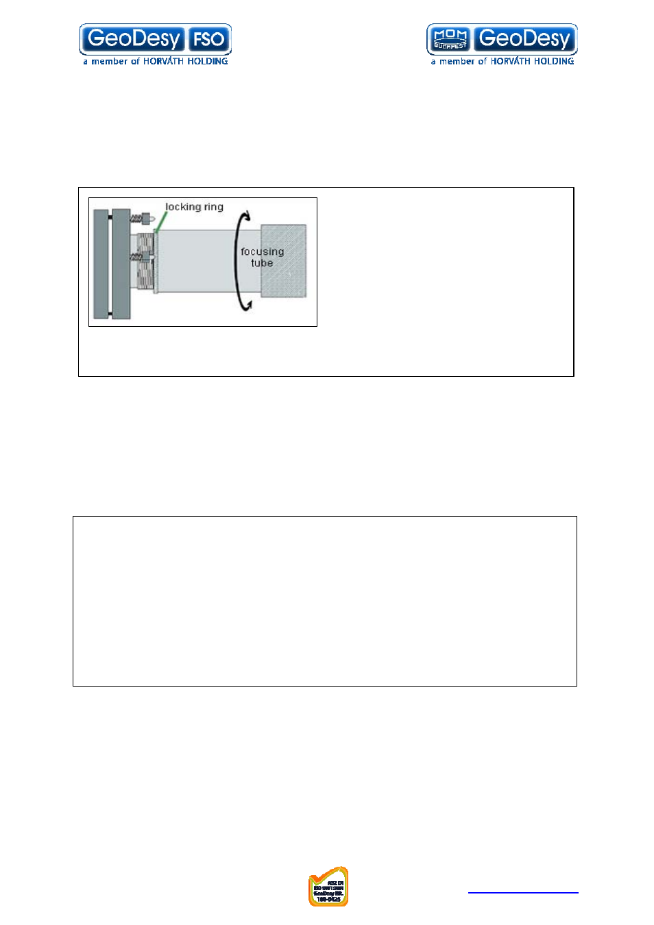
You can set the beam size turning the
focusing tube. First you have to loose the
shipping screws which are functioning as
transmitter fasteners, during shipment.
Then you have to loose the locking ring
which fastens the focusing tube. After that
you can manipulate with the beam size
turning the tube. If you turn it in clockwise
direction the diameter of the beam will
increase, and in counter-clockwise direction the beam size will decrease.
After you set the beam size, do not forget to lock the locking ring and tight up the two
shipping screws, but be careful that the transmitter does not move out its position!
To provide the excellent operation you need the following beam
sizes:
On 1500m distance the diameter of the beam should be 1,5 meters!
On 1750m distance the diameter of the beam should be 1,75 meters!
On 2000m distance the diameter of the beam should be 2 meter!
On 2250m distance the diameter of the beam should be 2,25 meters!
On 2500m distance the diameter of the beam should be 2,5 meters!
You can measure your beam size using a digital camera with infrared lenses. With
this you can see the beam behind the head on a surface (for example on a wall) and
there you can measure it. In that case if there are not any surfaces for beam
measuring, you can do it in the following method:
Face the remote side and check the beam with your camera. Move slowly to the
right in straight line until the picture of the beam, what you see in the camera, is
reducing, and sign that place. Do the same on the left side. Then you can measure
the distance between the two signed places. That will be the diameter of the beam.
If you can not use the camera efficiently enough, you can do it with your own eyes
too. The method is the same with one difference, the border of the beam is where
You cannot see the red dot on the transmitter lens of the remote side.
Repeat the setting on both sides with all of the transmitters!
End of the alignment
• Switch on all of the transmitters!
• Plug the motor controller cable back to the slot!
• Close up the covers of the heads!