Warning danger – Gast 1534 Series Oilless Vacuum Pumps and Compressors User Manual
Page 2
Motor Control
It is your responsibility to contact a qualified
electrician and assure that the electrical installation is
adequate and in conformance with all national and
local codes and ordinances.
Determine the correct overload setting required to
protect the motor (see motor starter manufacturer’s
recommendations). Select fuses, motor protective
switches or thermal protective switches to provide
protection. Fuses act as short circuit protection for the
motor, not as protection against overload. Incoming
line fuses help to withstand the motor’s starting current.
Motor starters with thermal magnetic overload or circuit
breakers protect motor from overload or reduced
voltage conditions.
The wiring diagram supplied with the product provides
required electrical information. Check that power
source is correct to properly operate the dual-voltage
motors.
Correct installation is your responsibility. Make sure
you have the proper installation conditions and that
installation clearances do not block air flow.
Blocking air flow over the product in any way can
cause the product to overheat.
Mounting
This product can be installed in any orientation.
Mounting the product to a stable, rigid operating
surface and using shock mounts will reduce noise and
vibration.
Accessories
The product’s internal intake and exhaust filters will
provide adequate filtration in most applications. Check
filters periodically and replace when necessary. The 32
and 34 Series models have internal intake and exhaust
filters. Some models in the 31 and 33 Series have
external intake and exhaust filters. All units should
have an intake and exhaust filter to prevent
contaminants from entering the pump or the pneumatic
system. Please consult your Gast
Distributor/Representative for additional filter
recommendations.
Plumbing
Remove plugs from the IN and OUT ports. Connect
with pipe and fittings that are the same size or larger
than the product’s threaded ports.
Electrical Connection
Brush type DC motors will need replacement brushes
after 500 hours to 1500 hours of operation. Contact
your Gast Distributor/Representative for replacement
brushes. Positive leads are red (+) and negative leads
are black (–).
Brushless DC motors with controls are preset from the
factory for single direction, uni-speed operation.
Positive leads are red (+) and negative leads are black
(–).
MFD and voltage ratings required for capacitors vary
with motor. If you are unsure of what capacitor is
required for your motor, contact your Gast
Distributor/Representative.
Install relief valves and gauges at inlet or outlet, or
both, to monitor performance. Check valves may be
required to prevent back streaming through the pump.
INSTALLATION
Your safety and the safety of others
is extremely important.
We have provided many important safety messages
in this manual and on your product. Always read
and obey all safety messages.
This is the safety alert symbol. This symbol
alerts you to hazards that can kill or hurt you and
others. The safety alert symbol and the words
“ DANGER” and “ WARNING” will precede all safety
messages. These words mean:
You will be killed or seriously injured if you don’t
follow instructions.
You can be killed or seriously injured if you don’t
follow instructions.
All safety messages will identify the hazard, tell you
how to reduce the chance of injury, and tell you
what can happen if the safety instructions are not
followed.
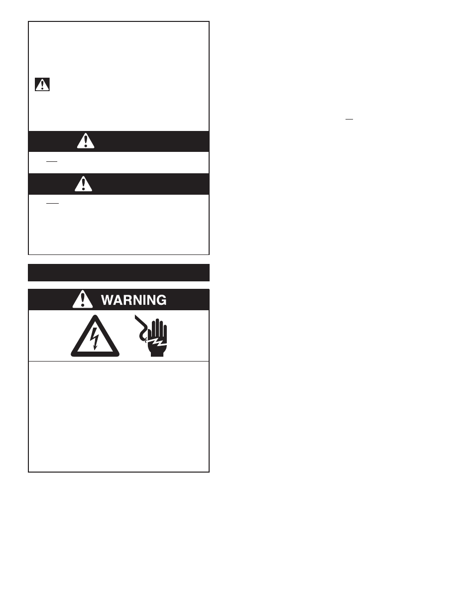
WARNING
DANGER
2
Electrical Shock Hazard
Disconnect electrical power at the circuit
breaker or fuse box before installing this
product.
Install this product where it will not come into
contact with water or other liquids.
Install this product where it will be weather
protected.
Electrically ground this product.
Failure to follow these instructions can result
in death, fire or electrical shock.
- 1034 Series Oilless Vacuum Pumps and Compressors 1033 Series Oilless Vacuum Pumps and Compressors 0533 Series Oilless Vacuum Pumps and Compressors 3032 Series Oilless Vacuum Pumps and Compressors 2032 Series Oilless Vacuum Pumps and Compressors 1532 Series Oilless Vacuum Pumps and Compressors 1032 Series Oilless Vacuum Pumps and Compressors 1531 Series Oilless Vacuum Pumps and Compressors