Bryant DURAPAC PLUS 551B User Manual
Page 41
—
41
—
Table 29 — Perfect Humidity™ Dehumidification System Sequence of Operation
and System Response — Dual Compressor Units
LEGEND
NOTE: On a thermostat call for W1, all cooling and dehumidification will be off.
F. Units With Power Exhaust
When the outdoor-air damper is modulated open, the two
end switches located in the actuator are tripped. The factory
settings are: switch no. 1 will close at 30% outdoor air;
switch no. 2 will close at 70% outdoor-air. Both switches are
field adjustable. As the outdoor-air damper opens, switch no.
1 closes, energizing a double-pole relay that starts fan no. 1.
As the outdoor-air damper continues to open, switch no. 2
will close, energizing a double-pole relay that starts fan no.
2. When the outdoor-air damper closes to a point below the
fan start points (30% fan no. 1, 70% fan no. 2), the respective
fan will be deenergized.
SERVICE
I. CLEANING
Inspect unit interior at the beginning of each heating and
cooling season or as operating conditions require.
A. Evaporator Coil
1. Turn unit power off and install lockout tag. Remove
evaporator coil access panel.
2. If EconoMi$er IV or accessory two-position damper is
installed, remove economizer or two-position damper
by disconnecting EconoMi$er IV plug and removing
mounting screws.
3. Slide filters out of unit.
4. Clean coil using a commercial coil cleaner or dish-
washer detergent in a pressurized spray canister.
Wash both sides of coil and flush with clean water.
For best results, back-flush toward return-air section
to remove foreign material.
5. Flush condensate pan after completion.
6. Reinstall economizer or two-position damper and filters.
7. Reconnect wiring.
8. Replace access panels.
B. Condenser Coils
Inspect coils monthly. Clean condenser coils annually, and as
required by location and outdoor-air conditions.
Clean 2-row coils as follows:
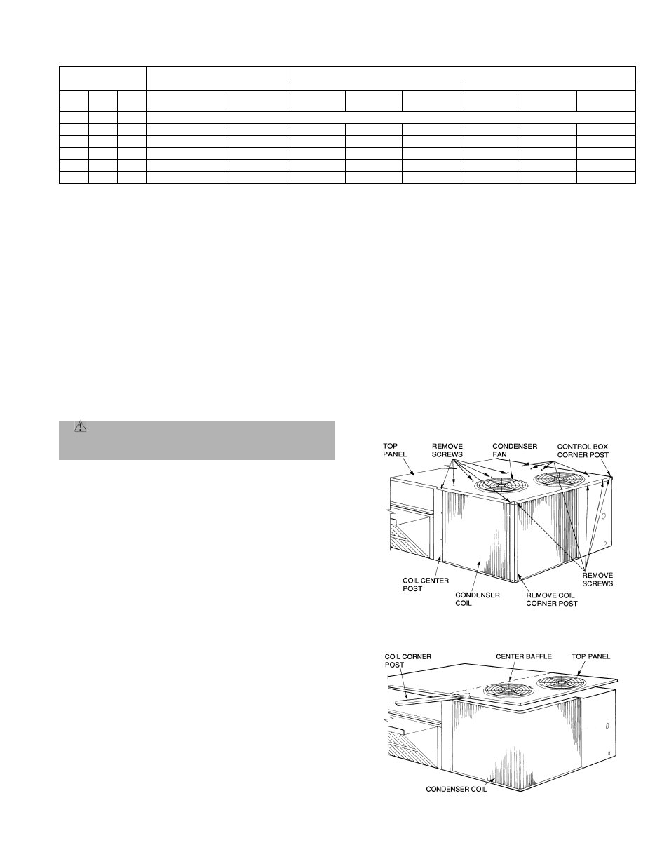
1. Turn off unit power and install lockout tag.
2. Remove top panel screws on condenser end of unit.
3. Remove condenser coil corner post. See Fig. 43. To
hold top panel open, place coil corner post between
top panel and center post. See Fig. 44.
4. Remove device holding coil sections together at
return end of condenser coil. Carefully separate the
outer coil section 3 to 4 in. from the inner coil section.
See Fig. 45.
5. Use a water hose or other suitable equipment to flush
down between the 2 coil sections to remove dirt and
debris. Clean the outer surfaces with a stiff brush in
the normal manner.
6. Secure the sections together. Reposition the coil sec-
tions, and remove the coil corner post from between
the top panel and center post. Install the coil corner
post and coil center post, and replace all screws.
THERMOSTAT
INPUT
ECONOMIZER FUNCTION
551B UNIT OPERATION
First Stage
Second Stage
H
Y1
Y2
OAT < Economizer
Set Point
Economizer
Compressor
1
Subcooling
Mode
Hot Gas
Reheat Mode
Compressor
2
Subcooling
Mode
Hot Gas
Reheat Mode
Off
—
—
Unit Operates Under Normal Sequence of Operation
On
On
On
No
Off
On
Yes
No
On
Yes
No
On
On
Off
No
Off
On
Yes
No
On
No
Yes
On
On
On
Yes
On
On
Yes
No
On
No
Yes
On
On
Off
Yes
On
On
No
Yes
On
No
Yes
On
Off
Off
No
Off
On
No
Yes
On
No
Yes
OAT
— Outdoor Air Temperature
CAUTION: When servicing unit, shut off all elec-
trical power to unit to avoid shock hazard or injury
from rotating parts.
Fig. 43 — Cleaning Condenser Coil
Fig. 44 — Propping Up Top Panel