Bryant DURAPAC PLUS 551B User Manual
Page 21
—
21
—
VII. STEP 7 — ADJUST EVAPORATOR-FAN SPEED
Adjust evaporator-fan rpm to meet jobsite conditions.
For units with electric heat, required minimum cfm is 2250
for 551B090 and 102 and 3000 for 551B120 and 150. See
Table 8 for exceptions.
Table 8 — Minimum Required Airflow Exceptions
Tables 9 and 10 show fan rpm at motor pulley settings for
standard and high-static motors. Tables 11 and 12 show
evaporator-fan motor data. See Tables 13 and 14 and Fig. 36
for accessory and option static pressure drops. Refer to
Tables 15-28 to determine fan speed settings.
Fan motor pulleys are factory set for speed shown in Table 1.
To change fan speeds:
1. Shut off unit power supply and install lockout tag.
2. Loosen belt by loosening fan motor mounting nuts.
See Fig. 37 and 38.
3. Loosen movable pulley flange setscrew (see Fig. 39).
4. Screw movable flange toward fixed flange to increase
rpm or away from fixed flange to decrease rpm.
Increasing fan rpm increases load on motor. Do not
exceed maximum speed specified in Table 1.
5. Set movable flange at nearest keyway of pulley hub
and tighten setscrew. (See Table 1 for speed change
for each full turn of pulley flange.)
To align fan and motor pulleys:
1. Loosen fan pulley setscrews.
2. Slide fan pulley along fan shaft.
3. Make angular alignment by loosening motor from
mounting plate.
To adjust belt tension:
1. Loosen fan motor mounting nuts.
2. Size 090 — Slide motor mounting plate away from fan
scroll for proper belt tension (
1
/
2
-in. deflection with
8 to 10 lb of force) and tighten mounting nuts (see
Fig. 37).
Sizes 102-150 — Slide motor mounting plate down-
ward to tighten belt tension. Secure motor mounting
plate nuts. See Fig. 38. Use
1
/
2
-in. deflection with 10 lb of
force.
3. Adjust bolt and nut on mounting plate to secure
motor in fixed position.
UNIT
551B
UNIT
VOLTAGE
HEATER
kW
UNIT
CONFIG-
URATION
REQUIRED
MINIMUM
CFM
120,150
208/230
42.4
Horizontal
3200
208/230
50.0
Horizontal
3200
460
50.0
Horizontal
or Vertical
3200
090-150
575
17.0
Horizontal
or Vertical
2800
34.0
2350
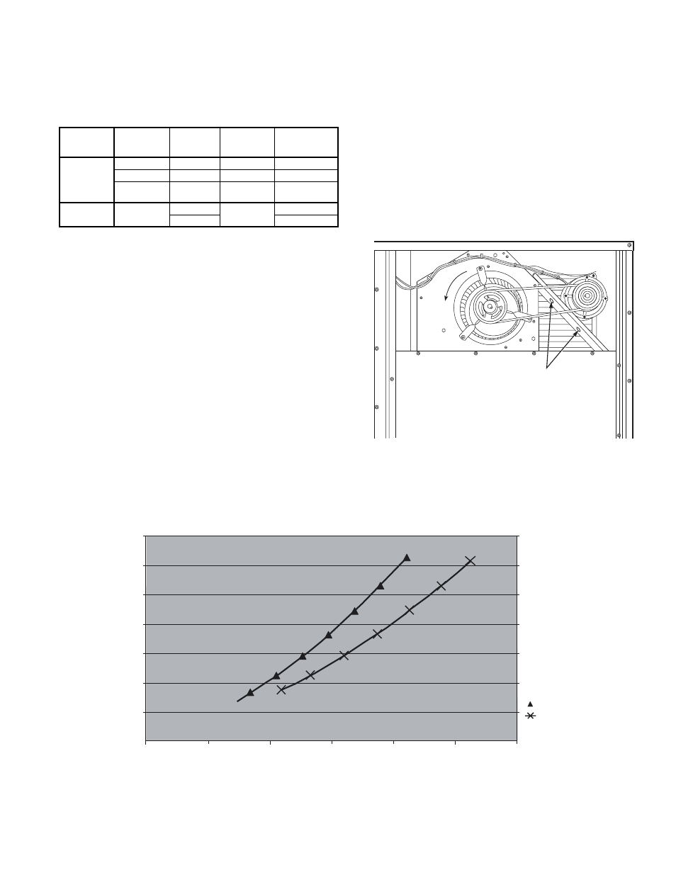
Fig. 37 — Typical Belt-Drive Motor Mounting for
Size 090
MOTOR MOUNTING
PLATE NUTS
6000
5000
4000
3000
2000
1000
0
0
0.05
0.1
0.15
0.2
0.25
0.3
0.35
DEL
T
A
P
IN. WG
7.5 ton
8.5, 10 & 12.5 ton
CFM
Fig. 36 — Perfect Humidity™ Dehumidification System Static Pressure Drop (in. wg)