Bryant DURAPAC PLUS 551B User Manual
Page 12
—
12
—
3. Use a wire nut to connect humidistat cable into low-
voltage wiring as shown in Fig. 13.
To install Thermidistat™ device:
1. Route Thermidistat cable through hole provided in
unit corner post.
2. Feed the wires through the raceway built into the cor-
ner post to the 24-v barrier located on the left side of
the control box. See Fig. 10. The raceway provides the
UL-required clearance between high and low voltage
wiring.
3. A field-supplied relay must be installed between the
Thermidistat device and the Perfect Humidity™ cir-
cuit (recommended relay: HN612KK324) Fig. 14. The
relay coil is connected between the DEHUM output
and C (common) of the unit. The relay controls the
Perfect Humidity solenoid valve and must be wired
between the Perfect Humidity fuse and the low-
pressure switch. Refer to the installation instructions
included with the Bryant Light Commercial Thermi-
distat device for more information.
Fig. 12 — Light Commercial Thermidistat Device
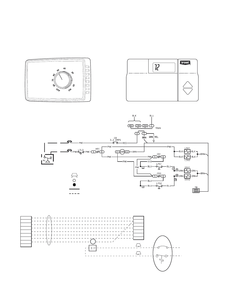
Fig. 13 — Typical Perfect Humidity Dehumidification System Humidistat Wiring (208/230-v Unit Shown)
CB
— Circuit Breaker
CR
— Cooling Relay
DHR
— Dehumidify Relay
DSV
— Discharge Solenoid Valve
HR
— Heater Relay
HU
— Humidistat
LPS
— Low Pressure Switch
LSV
— Liquid Solenoid Valve
LTLO — Low Temperature Lockout
TB
— Terminal Block
TRAN — Transformer
Field Splice
Terminal (Unmarked)
Splice
Factory Wiring
Field Control Wiring
LEGEND
ROOF TOP UNIT
R
C
Y1
Y2
G
W1
W2
PINK
PINK
RED
24 V
FROM
PERFECT HUMIDITY
SYSTEM LLSV
R1
T STAT WIRES
LCT
R
C
Y1
Y2
G
W1
W2
DEHUM
OC
R1
PERFECT HUMIDITY SYSTEM
PINK
LTLO
CB
3.2 AMPS
Fig. 14 — Typical Rooftop Unit with Perfect Humidity Dehumidification System with Thermidistat Device
LEGEND
CB
— Circuit Breaker
LCT
— Light Commercial Thermidistat Device
LLSV
— Liquid Line Solenoid Valve
LTLO
— Low Temperature Lockout
% RELATIVE HUMIDITY
Fig. 11 — Accessory Field-Installed Humidistat