Automatic water conditioners, Remier, Bypass valve - csm series only – Flint & Walling CSM, CVSM Two-Tank Water Softeners User Manual
Page 8
8
remier
remier
roducts
roducts
P
P
P
P
WATER TREATMENT
®
Automatic Water Conditioners
Premier Products Water Treatment | 95 North Oak St. | Kendallville, IN 46755 | 800-545-2206 | flintandwalling.com
Copyright © 2011 Flint & Walling All Rights Reserved.
IL1043
IL1044
IL1045
DIAgNOSTIC MODE
Supply
Water Exits
Supply
Water Enters
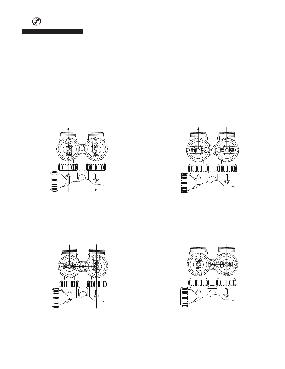
Figure 3
Diagnostic:
The inlet handle points in the direction of flow and the outlet handle
points to the center of bypass valve, system water pressure is allowed
to the control valve and the plumbing system while not allowing
water to exit from the control valve to the plumbing.
ByPASS OPERATION
IL1046
No
Water Exits
Supply Water is shut off
from the house and the
valve
SHUT OFF MODE
Figure 4
Shut Off:
The inlet handle points to the center of the bypass valve and the
outlet handle points in the direction of flow, the water is shut off to
the plumbing system. If water is available on the outlet side of the
softener it is an indication of water bypass around the system (i.e. a
plumbing connection somewhere in the building bypasses the system).
“Untreated”
Water Exits
Supply
Water Enters
Figure 2
Bypass:
The inlet and outlet handles point to the center of the bypass, the
control valve is isolated from the water pressure contained in the
plumbing system. Untreated water is supplied to the plumbing
system.
NORMAL OPERATION
“Treated”
Water Exits
Supply
Water Enters
Figure 1
Normal Operation:
The inlet and outlet handles point in the direction of flow indicated
by the engraved arrows on the control valve. Water flows through
the control valve during normal operation and this position also al-
lows the control valve to isolate the media bed during the regenera-
tion cycle.
Bypass Valve - CSM Series Only
The bypass valve is typically used to isolate the
control valve from the plumbing system’s water
pressure in order to perform control valve repairs or
maintenance. The bypass valve is particularly unique
in the water treatment industry due to its versatility
and state of the art design features. The full flow
bypass valve incorporates four positions, including
a diagnostic position that allows service personal to
work on a pressurized system while still providing
untreated bypass water to the facility or residence.
The completely non-metallic, all plastic design allows
for easy access and serviceability without the need for
tools.
The bypass body and rotors are glass filled Noryl
1
and
the nuts and caps are glass filled polypropylene. All
seals are self-lubricating EPDM to help prevent valve
seizing after long periods of non-use. Internal o-rings
can easily be replaced if service is required.
The bypass consists of two interchangeable plug valves
that are operated independently by red arrow shaped
handles. The handles identify the flow direction of
the water. The plug valves enable the bypass valve to
operate in four positions.
Noryl
1
is a trademark of General Electric