Automatic water conditioners, Remier, Typical w ater softener installation – Flint & Walling CSM, CVSM Two-Tank Water Softeners User Manual
Page 3
3
remier
remier
roducts
roducts
P
P
P
P
WATER TREATMENT
®
Automatic Water Conditioners
Premier Products Water Treatment | 95 North Oak St. | Kendallville, IN 46755 | 800-545-2206 | flintandwalling.com
Copyright © 2011 Flint & Walling All Rights Reserved.
Mineral
Tank
Assembly
Brine
Tank
Assembly
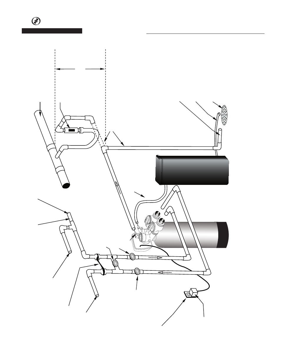
Sanitary Drain, Floor Drain or Laundry
Tubs are acceptable.
Do not make a direct connection to the drain. An air gap must be present.
Brine
Tank Overflow drain 1/2” ID
diameter minimum size (gravity flow)
Cold hard water inlet 30 p.s.i. minimum pressure 3/4” minimum pipe size
Maximum drain pipe elevation above drain port is 5 ft.
High Pressure
W
arning:
If feedwater pressure is known to be above 125 PSI, it is strongly recommended that a pressure reducing valve be installed at this point.
Hard water to Sprinklers and any dersired unsoftened fixtures
Ground Strap
Softened
W
ater Outlet
Manual Outlet
Valve
(optional)
Brine Line
Tubing
110-125
Volt
Continuous Power Supply
Transformer
Manual Bypass
Valve
(Normally Closed) (optional)
Manual Inlet
Valve
(optional)
Drain Port
Drain line 1/2” diameter ID minimum size
Connection to sanitary sewer line (optional)
Air gap device
Sanitary sewer line
Drain
Trap
Drain
IL1054
Typical W
ater Softener Installation