7 maintenance and care, 8 repair, 9 accessories – Festo DGC-K-18 … -80 User Manual
Page 4: 10 trouble-shooting, 11 technical data
7
Maintenance and care
• Clean the belt system if required with a soft cloth.
• Avoid cleaning agents which will damage the belt system, which is made of PU.
Excessive rubbing or the use of grease-solvent cleaning agents (e.g. soap suds)
will damage the grease layer.
8
Repair
• Recommendation: Send the product to our repair service.
This will ensure that special attention is given to the necessary fine tuning and
testing.
• Information about spare parts and accessories:
(
www.festo.com/spareparts).
9
Accessories
Note
• Please select the corresponding accessories from our catalogue:
(
www.festo.com/catalogue/DGC-K).
10
Trouble-shooting
Malfunction
Possible cause
Remedy
Uneven movement of
the slide
One-way flow control valve not
installed correctly
If possible reduce the exhaust
(not the supply air)
Malfunctions in
position sensing
Ferritic parts in the vicinity of the
proximity sensor
Use parts consisting of
non-magnetic materials or
observe minimum distances
(
5.3. Installation, electric)
Heavy leakage
Linear actuator integrated in a
distorted manner
Fasten the linear actuator to a flat
base.
Seal worn
Replace worn parts:
– yourself with wearing parts kit
– send product to Festo for
repairs
Sealing band pressed/sucked in
When the linear actuator is
unpressurized:
loosen the tubing connection and
move the slide by hand through
the entire stroke twice (if
necessary, move fixed stops into
the end position)
Avoid low pressure in the piston
chamber (e.g. only move the
unpressurised slide slowly)
Linear actuator does
not achieve the
desired speed
Air volume not sufficient
– Increase connection
cross-section
– Connect volumes in series
High friction or counteracting
force
Observe limits
Fig. 17
11
Technical data
Size
18
25
32
40
50
63
80
Pneumatic connection
M5
G
Á
G
¼
G
Å
G½
Mode of operation
Double-acting
Mounting position
Any
Operating medium
Compressed air to ISO 8573-1:2010 [7:–:–]
Notes regarding operating/
control medium
Lubricated operation possible (required during subsequent
operation)
Operating pressure
[bar]
2 … 8
1.5 … 8
Ambient temperature
[°C]
–10 … +60
Theoretical force at 6 bar [N]
153
295
483
754
1178
1870
3016
Speeds (min … max)
[m/s]
0.05 … 2
0.04 … 2
0.03 … 2
Cushioning length, PPV
[mm]
16
18
20
30
30
30
83
Cushioning
PPV
Pneumatic cushioning, adjustable at both ends
Max. impact energy
Diagrams in the catalogue
Materials
Profile tube, slide
Anodised aluminium
End cap
Aluminium
Piston
Aluminium, POM
Aluminium
Piston seal, cushioning seal,
sealing band
PU
Wiper seal, band reverser
POM
Cover strip
Steel
PU
Vapour disc
Nitrile rubber
Fig. 18
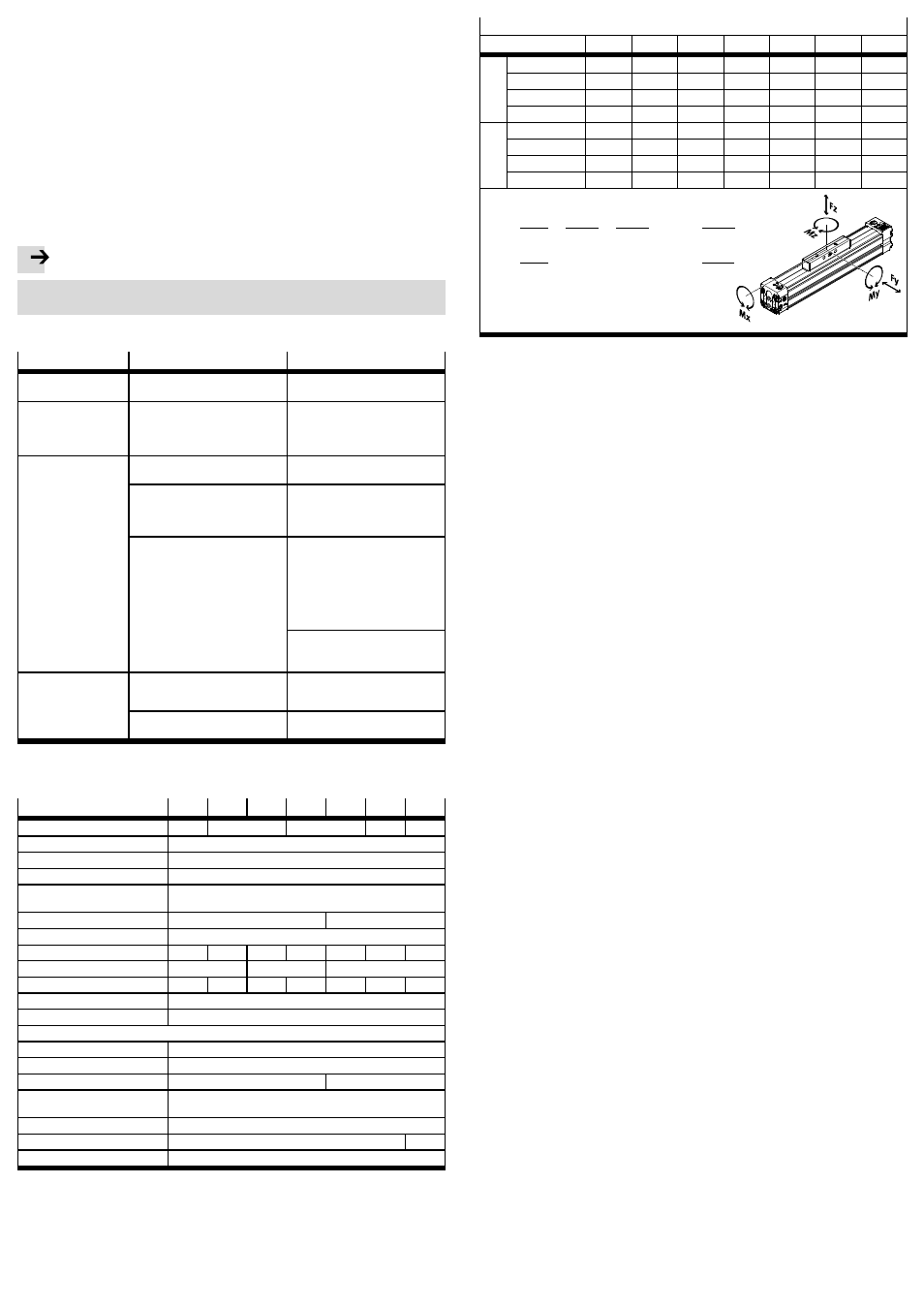
Permissible force and torque loading
Size
18
25
32
40
50
63
80
GK
Fz
max
[N]
120
330
480
800
1200
1600
2500
Mx
max
[Nm]
0.8
1.2
1.9
3.8
6
5.7
32
My
max
[Nm]
11
20
40
60
120
150
400
Mz
max
[Nm]
1
3
5
8
15
24
100
GV
Fz
max
[N]
120
330
480
800
1200
1600
–
Mx
max
[Nm]
1.6
2.4
3.8
7.6
12
11.4
–
My
max
[Nm]
22
40
80
120
240
300
–
Mz
max
[Nm]
2
6
10
16
30
48
–
0, 4
× Fz
Fz
max
+ Mx
Mx
max
+
My
My
max
+ 0, 2 × Mz
Mz
max
≤ 1
Formulas for combined loads:
Fz
Fz
max
≤ 1
Mz
Mz
max
≤ 1
Fig. 19