3 installation, electric, 4 installation of accessories, 6 commissioning – Festo DGC-K-18 … -80 User Manual
Page 3: 1 commissioning the complete system, 2 preparing for commissioning, 3 carrying out commissioning
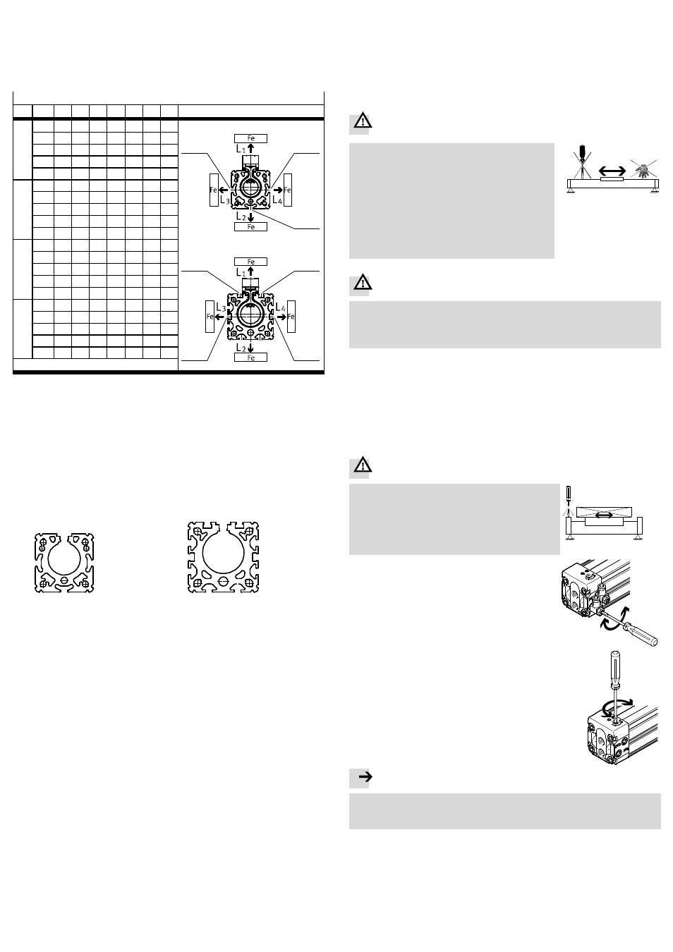
5.3 Installation, electric
Position scanning with proximity sensors SME/SMT:
• Use grooves (S) for mounting the proximity sensors (
Fig. 12).
• Observe the minimum distances between ferritic loads and the proximity
sensors.
In this way you will avoid incorrect switching as a result of external influences.
Minimum clearances [mm]
POS 18 25 32 40 50 63 80
L1
1
0
0
0
0
0
0
0
2
1
3
DGC-K-18/-25
4
5
DGC-K-32 ... -80
2
1
2
0
0
0
0
0
0
0
3
0
0
–
–
–
–
–
4
–
–
10
30
10
20
10
5
–
–
10
30
10
20
10
L2
1
10
0
0
0
0
0
0
2
10
0
0
0
0
0
0
3
30
10
–
–
–
–
–
4
–
–
0
0
0
0
0
5
–
–
0
0
0
0
0
L3
1
30
10
10
30
10
20
10
2
0
0
0
0
0
0
0
3
10
0
–
–
–
–
–
4
–
–
0
0
0
0
0
5
–
–
0
0
0
0
0
L4
1
0
0
0
0
0
0
0
2
30
10
10
30
10
20
10
3
10
0
–
–
–
–
–
4
–
–
0
0
0
0
0
5
–
–
0
0
0
0
0
Fig. 11 (POS = position of proximity switch)
Laying the cables for the proximity switches:
• Observe that the cables for the proximity switches can be guided through the
groove.
5.4 Installation of accessories
• Use the following grooves for attachment of the accessories (
Fig. 12).
S = Slot for proximity sensor
N = Slot for mounting accessories
DGC-K-18/-25
DGC-K-32 ... -80
S/N
S/N
S/N
S
S
N
N
N
N
S
S
N
N
Fig. 12
• Use the slot covers (
www.festo.com/catalogue):
– to prevent contamination in the slots (S)
– for locking the cables of proximity switches.
6
Commissioning
6.1 Commissioning the complete system
• Slowly pressurise the system as a whole.
In this way you will prevent sudden uncontrolled movements.
For slow start-up pressurisation, use start-up valve type HEL.
6.2 Preparing for commissioning
Before each commissioning and in operation:
Warning
Fast moving parts can cause injury to people in the
environment of the DGC-K.
• Make sure that, in the travel range
– Nobody can reach into the path of the movable
components (e.g. by providing a protective
guard)
– There are no foreign objects in the path of the
moving components.
It should not be possible to touch the DGC-K until
the load has come to complete rest.
Fig. 13
Warning
Without external cushioning devices the DGC-K may be damaged if the maximum
values specified in the catalogue are exceeded.
• Make sure that the limit values are not exceeded even in the event of malfunc-
tions.
At medium or large useful loads or high speeds:
• Use the configuration tool “DGC-QuickCalc” for pneumatic drives in the support
portal (
www.festo.com/sp).
• Make sure that cushioning devices are of sufficient size.
Without external cushioning devices the DGC-K will withstand maximum speeds
and useful loads as per catalogue specifications or table (
Fig. 18).
6.3 Carrying out commissioning
Warning
Risk of collision!
• Note that, for the load geometries with projection,
the regulating screws
2 of the DGC-K may only be
turned when the slide is at rest.
Fig. 14
1. Close the one-way flow control valves
– for both sides at first completely
– then one rotation open again.
Fig. 15
Using the internal end position cushioning PPV:
2. Close the adjusting screws for the internal end pos-
ition cushioning PPV
2
– on both sides at first completely
– then one rotation open again.
Fig. 16
Note
To set the end position cushioning:
• Make sure that the slide reaches the end positions without striking hard
against them or bouncing back.
3. Pressurize the DGC-K slowly as follows:
– at first on both sides simultaneously. The slide will then move slightly to a
centre of equilibrium.
– Then exhaust the DGC-K on one side.
In this way you can avoid peak loadings on the DGC-K and in the compressed
air network.
4. Start a test run.
5. Check whether the speed must be modified (
5.2 Installation, pneumatic).