2 installation, pneumatic – Festo DGC-K-18 … -80 User Manual
Page 2
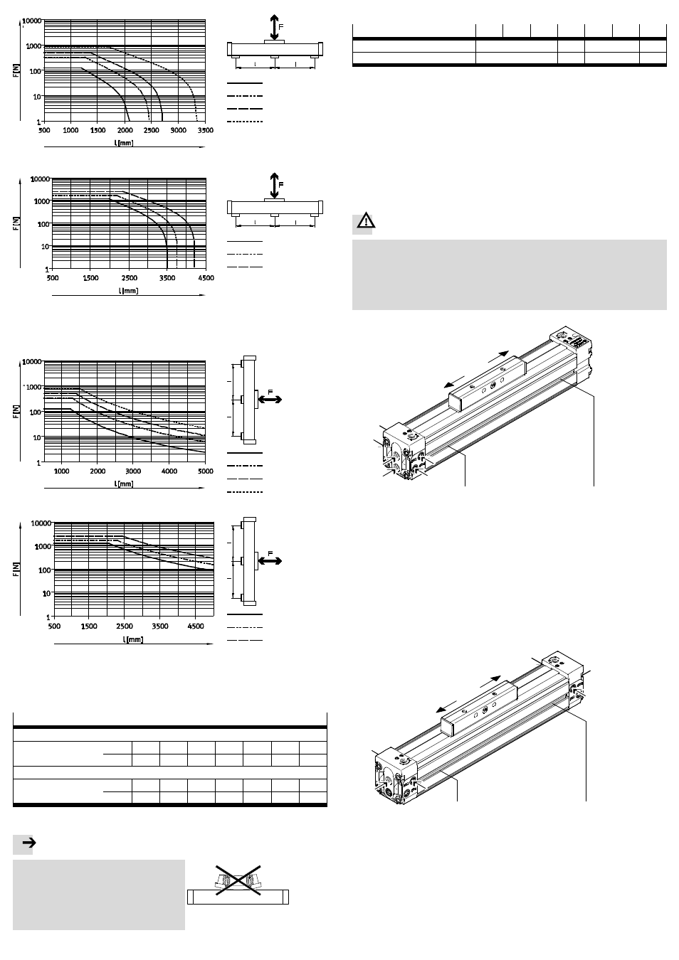
DGC-K-18
DGC-K-25
DGC-K-32
DGC-K-40
DGC-K-50
DGC-K-63
DGC-K-80
Fig. 4
Required support spacing (l) with horizontal mounting orientation
DGC-K-18
DGC-K-25
DGC-K-32
DGC-K-40
DGC-K-50
DGC-K-63
DGC-K-80
Fig. 5
Required support spacing (l) with horizontal mounting orientation
• Note the tightening torques when attaching.
Tightening torques of the mounting screws
Direct mounting on thread
9
Size
18
25
32
40
50
63
80
[Nm]
2.5
3
4
5
8
14
45
Slot attachments (e.g. with MUP central support)
Size
18
25
32
40
50
63
80
[Nm]
3
3
4.5
5.5
18
18
18
Fig. 6
Note
With hard and stiff useful loads:
If the slide
3 is bent due to a buckled use-
ful load, it will reduce the service life of the
drive.
• Make sure the mounting surface of the
useful load is even.
Fig. 7
• Observe the tightening torques for the threads
4 in the slide.
Size
18
25
32
40
50
63
80
Thread
M5
M6
M8
M12
Tightening torques
[Nm]
3.5
6
12
30
Fig. 8
Effective loads with own guide:
• Adjust the guides of the effective load and of the DGC-K so that they are exactly
parallel.
In this way can you avoid overloading on the slide (Permissible forces
11 Technical data).
The driver DARD-L1 offers a torque-free and almost backlash-free power trans-
mission (
www.festo.com/catalogue).
5.2 Installation, pneumatic
For installation in a vertical or inclined position:
Warning
If there is a pressure drop, the movable load will drop down:
Danger of crushing!
• Check whether HGL non-return valves are necessary.
In this way, you can prevent the movable load from sliding down suddenly.
• Check whether safety measures are required to prevent sinking as a result of
leakage (e.g. toothed latches or moveable bolts).
A(2)
A(1)
A(2)
W(2)
1
2
A(1)
W(1)
1
2
W = compressed air supply ports from
the plant
1 = end position on the connection
side
1 = movement to the connection side
A = alternative connections
2 = end position connection side
2 = movement to the connection side
Fig. 9
• Select the suitable compressed air supply ports.
In addition to the supply ports provided at the factory (W), there are also the
alternative ports (A). These are fitted with plug screws.
For the linear actuator DGC-K of variant D2, the compressed air supply can be
made on both sides.
A(1)
W(1)
A(2)
A(2)
W(2)
1
2
A(1)
1
2
W = compressed air supply ports from
the plant
1 = end position on the connection
side (left)
1 = movement to the connection
side (left)
A = alternative connections
2 = end position connection
side (right)
2 = movement to the connection
side (right)
Fig. 10
For setting the speed:
• Rotate the one-way flow control valves GRLA into the supply ports.