Ab c – EUCHNER Hinge ESH Re-adjustable User Manual
Page 3
Operating Instructions Safety Hinge ESH Re-adjustable
Correct use
The safety hinges ESH are interlocking devices
without guard locking for monitoring movable safety
guards, such as doors or covers on machinery or
systems.
In combination with a separating safety guard, this
safety component prevents dangerous machine
movements from being performed for as long as the
safety guard is open. A stop command is triggered
if the safety guard is opened during the dangerous
machine function.
For the control system, this means that
starting commands which cause hazardous situ-
ations must become active only when the safety
guard is in the protective position.
The safety switches series ESH comply with the
regulations of EN 60947-5-1 Annex K and comply
with the requirements of the employers' liability
insurance associations for machines, installations
and personnel protection.
Before safety switches are used, a risk assessment
must be performed on the machine in accordance
with
EN ISO 13489-1, Safety of machinery. Safety re-
lated parts of control systems. General principles
for design
EN ISO 14121, Safety of machinery. Risk assess-
ment. Principles
IEC 62061, Safety of machinery. Functional safety
of safety-related electrical, electronic and program-
mable electronic control systems.
Correct use includes compliance with the relevant
requirements for installation and operation, in
particular
EN ISO 13489-1, Safety of machinery. Safety re-
lated parts of control systems. General principles
for design
EN 1088, Safety of machinery. Interlocking
devices associated with guards. Principles for
design and selection
EN 60204-1, Safety of machinery. Electrical equipment
of machines. General requirements.
Important:
The user is responsible for safe integration of the
device in a safe overall system. For this purpose
the overall system must be validated, e.g. in ac-
cordance with EN ISO 13849-2.
If the simplified method according to section 6.3
EN ISO 13849:2008 is used for validation, the
Performance Level (PL) may be reduced if several
devices are connected one after the other.
If a product data sheet is included with the product,
the information on the data sheet applies in case of
discrepancies with the operating instructions.
Safety precautions
Safety switches fulfill a personal protection func-
tion. Incorrect installation or tampering can lead
to severe injuries to personnel.
Safety switches must not be bypassed (bridg-
ing of contacts), turned away, removed or
otherwise rendered ineffective.
On this topic pay attention in particular to the
measures for reducing the possibility of bypassing
according to EN 1088:1995.A2:2008, sec. 5.7.
A complete safety-oriented system gener-
ally consists of several signaling devices,
sensors, evaluation units and concepts for safe
shutdown. The manufacturer of a machine or
installation is responsible for correct and safe
overall function.
Mounting, electrical connection and setup only
by authorized personnel.
Function
The safety switch signals that the safety guard is
closed. The switch does not perform guard locking!
Mounting
Safety switches must be arranged such that they are
adequately secured against movement.
The maximum load given must not be exceeded.
The safety hinge is not allowed to be used as a me-
chanical limit for the door pivot radius.
You can obtain suitable plain hinges without switches
from EUCHNER under order no. 096 007.
To meet these requirements:
The fixings must be reliable and must also require
the use of a tool to undo them.
Mount the safety switch positively.
Fit switches using M6 screws.
Proceed as follows:
Fasten hinges to the frame. The fastening points
for the two hinges must be as far apart as pos-
sible. The axes around which the hinges pivot
must be exactly in a line.
Move door to the required position and secure
against slipping or falling.
Fit door to the hinges.
4. Fix door in closed position.
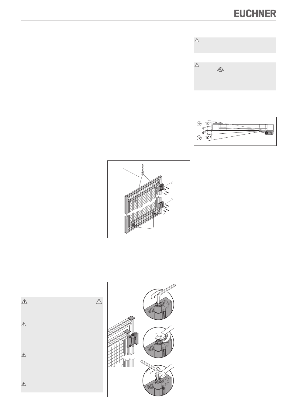
5. Adjust operating point
A Undo hex socket head screw.
B Adjust operating point using the hex nut.
When the operating point is reached, the
indication changes position in the window.
C Tighten hex socket head screw to 8 Nm.
During this process lock hex nut.
1.
2.
3.
If the door should go out of adjustment, the operat-
ing point can be re-adjusted.
For protection against tampering, the black
protective cap must be fitted to the hex nut.
The cap must engage
Electrical Connection
For use and applications as per the require-
ments of
, a class 2 power supply or a
class 2 transformer according to UL1310 or
UL1585 must be used. As an alternative, a low
voltage power supply according to UL508 table
32.1 can be used.
Connect M12/5-pin plug connector.
You can obtain suitable connection cables from
EUCHNER under order no. 073461.
Setup
Mechanical function test
Open door and check operating point. The hinge
must switch at the latest 4° from the closed
position (fixing position). The switching contacts
are positively opened after approx. 10°.
Check whether the door moves freely.
Electrical function test
Close the safety guard.
Start the machine.
Check whether the machine stops when the
safety guard is opened.
Switch off the machine.
Open the safety guard. The machine must not
start when the safety guard is open!
When the safety guard is open, the safety switch
must be actuated in any safety guard position.
Protection against environmental effects
A lasting and correct safety function requires pro-
tection against the penetration of foreign bodies
such as swarf, sand, blasting shot, etc. Only use
solvent-free and acid-free cleaning agents to clean
the safety switch!
Service and inspection
No servicing is required, but regular inspection of
the following is necessary to ensure trouble-free
long-term operation:
correct switching function
secure mounting of components
dirt and wear
loose plug connectors.
If damage or wear is found, the complete switch
must be replaced. Replacement of individual parts
or assemblies is not permitted!
Note: The year of manufacture can be seen in the
bottom, right corner of the rating plate.
1.
2.
1.
2.
3.
4.
5.
l = max.
4 x M6
Support
Support/adjustment aid
A
B
C