Operating instructions safety switches stm – EUCHNER STMxxx User Manual
Page 6
Operating Instructions Safety Switches STM...
V
h
31
2,5
∅
4,7
79
15,5
22
21
4
36
42
∅
5,2
∅4,2
96
M=0,5 Nm
A
9
15,5
20,5
4
10,5
B
37,5
31,5
0,3
B
0,3
A
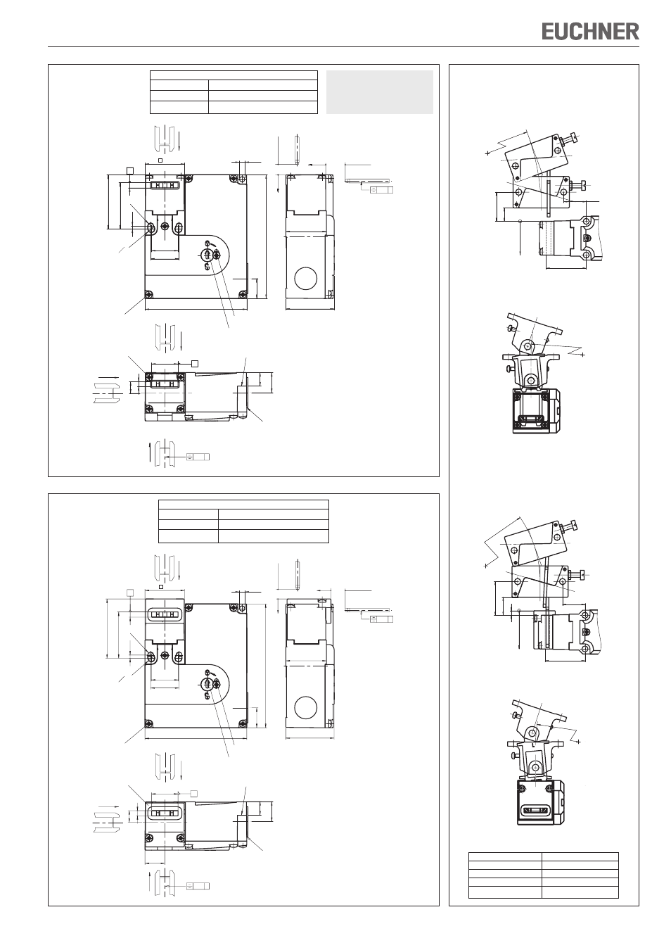
Figure 3: Dimension drawing STM.A., ...B., ...E., ...F., ...N., ...O.; minimum travel and overtravel
Insertion depth
Screw M5 for fixed
positioning for
safety applications
Inser
tion depth
Mechanical release
Standard
actuator S
Thread depending on
design:
- M20 x 1.5
- NPT ½“
M = 0.6 Nm
Locking screw (M = 0.5 Nm)
Protection against
twisting (screw M4)
Figure 4: Dimension drawing STM.C., ...D., ...G., ...H., ...P., ...Q. with insertion funnel; minimum travel and overtravel
Necessary minimum travel + permissible overtravel
Approach direction
Standard actuator S
Horizontal (h)
24,5 + 5
Vertical (v)
24,5 + 5
31
2,5
∅
5,2
∅
4,7
79
15,5
22
21
96
4
46
36
M=0,5 Nm
A
9
15,4
4
20,5
B
37,5
31,5
h
V
0,3
B
0,3
A
∅4,2
15,5
10,5
Insertion depth
Screw M5 for fixed
positioning for safety
applications
Inser
tion depth
Mechanical release
Actuator L
Thread depending on
design:
- M20 x 1.5
- NPT ½“
M = 0.6 Nm
Locking screw (M = 0.5 Nm)
Protection against
twisting (screw M4)
Necessary minimum travel + permissible overtravel
Approach direction
Actuator L
Horizontal (h)
28,5 + 5
Vertical (v)
28,5 + 5
Warning:
The actuator S is only allowed
to be used for STM switches
without insertion funnel.
Figure 5: Min. door radii
Actuator type
Door radius min. [mm]
Actuator S-G...
300
Actuator S-W...
300
HINGED ACTUATOR S-OU...
200
HINGED ACTUATOR S-LR...
200
Hinged actuator S-OU-LN for
insertion funnel
Hinged actuator S-LR-LN for
insertion funnel
16
30
R >
200
35,5
4
28,5 +5
20
R>200
39
Hinged actuator S-OU-SN
Hinged actuator S-LR-SN
24,5 +5
12
26
35,5
R >
20
200
R>200