Operating instructions safety switch stp-bi – EUCHNER STP-BIxxx User Manual
Page 4
Operating Instructions Safety Switch STP-BI...
EUCHNER GmbH + Co. KG Kohlhammerstraße 16 D-70771 Leinfelden-Echterdingen Tel. +49 711 7597-0 Fax +49 711 753316 [email protected] www.euchner.de
Correct use
Safety switches series STP-BI are electromagnetic
interlock devices with guard locking.
In combination with a safety guard and the machine
control, this safety component prevents the safety
guard from being opened while a dangerous machine
movement is being performed.
For the control system, this means that
f
starting commands which cause hazardous situ-
ations must become active only when the safety
guard is in protective position and the guard lock-
ing is in locked position.
The locked position of the guard locking must be
released only when the hazardous situation is no
longer present.
Before safety switches are used, a risk assessment
must be performed on the machine in accordance
with
f
EN ISO 13849-1, Safety of machinery. Safety re-
lated parts of control systems. General principles
for design
f
EN ISO 14121, Safety of machinery. Risk assess-
ment. Principles
f
IEC 62061, Safety of machinery. Functional safety
of safety-related electrical, electronic and program-
mable electronic control systems.
Correct use includes compliance with the relevant
requirements for installation and operation, in
particular
f
EN ISO 13849-1, Safety of machinery. Safety re-
lated parts of control systems. General principles
for design
f
EN 1088, Safety of machinery. Interlocking
devices associated with guards. Principles for
design and selection
f
EN 60204-1, Safety of machinery. Electrical equip-
ment of machines. General requirements.
Important:
f
The user is responsible for the integration of the
device into a safe overall system. For this purpose,
the overall system must be validated, e.g. in ac-
cordance with EN ISO 13849-2.
f
If the simplified method according to Section 6.3
EN ISO 13849-1:2008 is used for validation, the
Performance Level (PL) may be reduced if several
devices are connected one after the other.
f
If a product data sheet is included with the product,
the information on the data sheet applies in case
of discrepancies with the operating instructions.
The STP-BI has an additional function intended to
prevent
f
persons from unintentionally locking themselves
inside if the safety door is open in case of a power
failure or if the machine is switched off
f
the deactivation of the activated guard locking in
case of a power failure.
Important: This additional function is not a safety
function!
Safety precautions
Safety switches perform a personal protection
function. Incorrect installation or tampering can
lead to severe injuries to personnel.
Safety components must not be bypassed
(bridging of contacts), turned away, removed
or otherwise rendered ineffective.
On this topic pay attention in particular to the
measures for reducing the possibility of bypassing
according to EN 1088:1995.A2:2008, Sec. 5.7.
The switching operation may only be triggered
by actuators specially provided for this purpose
which are permanently connected to the
protective guard.
Mounting, electrical connection and setup only
by authorized personnel.
Function
The safety switch permits the locking of movable
safety guards.
In the switch head there is a rotating cam that is
blocked/released by the guard locking pin. The
guard locking pin is moved on the insertion/removal
of the actuator and on the activation/deactivation of
the guard locking. During this process the switching
contacts are actuated.
If the cam is blocked, the actuator cannot be pulled
out of the switch head
Guard locking active.
The switch has, in addition to the mechanical/
electromagnetic guard locking, fixing for the guard
locking pin. The guard locking pin is held in its cur-
rent position if the operating voltage is not present.
The guard locking pin can only be moved by applying
the operating voltage.
In case of interruption of the power supply (operat-
ing voltage) for the switch or if the machine, e.g.,
is switched off for servicing, the guard locking pin
is held in its last position. As a result the safety
door is either completely locked or it can be closed
and opened as often as required without the guard
locking pin locking.
Position monitoring of the safety guard and guard
locking monitoring are performed via the same
switching element.
Actuator version
Actuator S for safety switches STP without inser-
tion funnel.
Actuator L for safety switches STP with insertion
funnel.
Version STP3-BI
(guard locking by spring force)
The guard locking pin is held in the locked position
by spring force and unlocked by electromagnetic ac-
tuation (control voltage). The spring interlock guard
locking functions in accordance with the closed-
circuit current principle. The safety guard cannot be
opened immediately in the event of interruption of
the power supply (operating voltage) to the switch.
f
Closing safety guard and activating guard
locking
The guard locking pin is released by insertion of the
actuator into the safety switch.
STP3-BI: The guard locking pin is moved to locked
position by spring force.
f
Deactivating guard locking, opening safety
guard
STP3-BI (with door monitoring contact): The guard
locking pin releases the cam when the solenoid
operating voltage is applied.
For switching function see Figure 2, Column 2, Door
closed and not locked
The actuator can be removed.
On removal of the actuator, the door monitoring
contact switches and signals that the safety guard
is open (see Figure 2, Column 3, Door open).
Mechanical release
In the event of malfunctions, the guard locking can
be deactivated using the mechanical release, irre-
spective of the state of the solenoid (see Figure 3).
f
Unscrew locking screw.
f
Using a screwdriver, turn the mechanical release
by around 180° in the direction of the arrow.
The mechanical release or the mechanical key
release must be returned to its original position and
sealed after use (for example, with sealing lacquer
or using wire).
Mounting
Safety switches and actuators must not be used
as an end stop.
Mount the safety switch only in assembled
condition!
Caution! Risk of burns due to high surface tem-
perature at ambient temperatures above 40 °C!
Protect switch against touching by personnel
or contact with inflammable material.
Assemble the safety switch so that
f
access to the switch is difficult for operating per-
sonnel when the safety guard is open.
f
it is possible to operate the mechanical release
and check and replace the safety switch.
f
the escape release can be actuated from the
hazard area.
Fit an additional end stop for the movable part of
the safety guard.
f
Insert the actuator in the actuating head.
f
Mount the safety switch positively.
f
Permanently connect the actuator to the safety
guard so that it cannot be detached, e.g. using the
enclosed non-removable screws, rivets or welding.
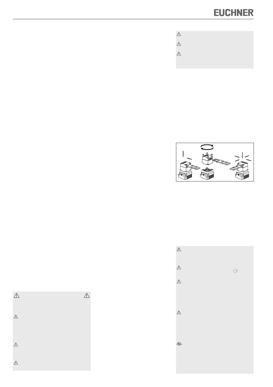
Changing the actuating direction
Figure 1: Changing the actuating direction
f
Remove the screws from the actuating head.
f
Set the required direction.
f
Tighten the screws with a torque of 0.6 Nm.
f
Cover the unused actuating slot with the enclosed
slot cover.
Protection against environmental effects
A lasting and correct safety function requires that
the actuating head must be protected against the
penetration of foreign bodies such as swarf, sand,
blasting shot, etc.
Electrical connection
When choosing the insulation material and wire
for the connections, pay attention to the over-
temperature in the housing (depending on the
operating conditions)!
Only switching contacts marked with the posi-
tively driven NC contact symbol are to be
used for the safety circuit.
For switching elements with four positively
driven NC contacts only the contacts 21-22
and 41-42 are actuated on activating and de-
activating the guard locking. In applications with
potentially hazardous states (e.g. overtravelling
movements), contact 21-22 and/or 41-42 must
always be integrated into the safety circuit.
In order to avoid EMC interference, the physical
environmental and operating conditions at the
installation site of the device must comply with
the requirements according to the standard EN
60204-1:2006, Section 4.4.2 (EMC).
For STP-BI with plug connector:
For use and applications as per the requirements of
, a class 2 power supply or a class 2 transformer
according to UL1310 or UL1585 must be used.
Connection cables for safety switches installed at
the place of use must be separated from all moving
and permanently installed cables and un-insulated
active elements of other parts of the system which
operate at a voltage of over 150 V. A constant
A
D
B
C