Enerpac PR-Series Air User Manual
Page 6
WARNING: Failure to observe the following instructions
could allow load to shift or drop. Serious personal injury
and/or property damage may result.
When using PRE Series extensions and/or PRS Series spacers,
always obey the following rules:
• For loads up to 60 tons [54 metric tons]: Any two PRE Series
extensions may be included in the stacking arrangement,
provided that the maximum stack height (See Table 5) is not
exceeded and the following exceptions are observed:
1) Jack model
PRAMA06014L:
Only one PRE18 extension
can be included in the stacking arrangement.
2) All jack models ending in “16L”
:
Only one PRE11, PRE14
or PRE18 extension can be included in the stacking arrangement.
3) All jack models ending in “27L”
: Extensions PRE14 and
PRE18 cannot be included in the stacking arrangement.
These
extensions are designed for short stroke jacks only (models
ending in “14L” and “16L”).
•
For loads over 60 tons [54 metric tons], or strokes over
14 inches [356 mm]: Only one PRE Series extension and
one PRS Series spacer can be included in the stacking
arrangement.
• Never exceed 3 inches [76 mm] in total spacer height.
• Never exceed the maximum additional stack height for your
jack model. Refer to Table 5, dimension “X”.
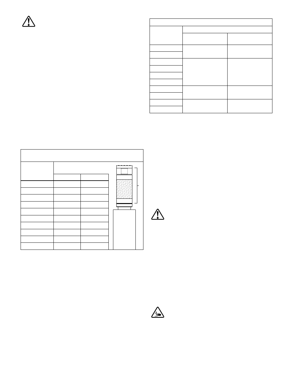
Table 5 - Maximum Additional Stack Height Using
Optional PRE Series Extensions and PRS Series Spacers
Jack Model
Maximum Additional Stack
Height (dimension “X”)
X
inches
mm
PRAMA06014L
32
813
PRAMA06027L
11
279
PRAMA10016L
21
533
PRAMA10027L
11
279
PRASA10016L
21
533
PRASA10027L
11
279
PRASA15016L
21
533
PRASA15027L
11
279
PRASA20016L
21
533
PRASA20027L
11
279
5.5 Load Caps
A non-swivel load cap is included with the jack as standard
equipment. A swivel load cap is available as an optional
accessory. Refer to Table 6 for a list of load cap model numbers.
IMPORTANT: Use a swivel load cap to properly engage angled
lifting points. A swivel load cap should always be used when the
amount of misalignment between the standard load cap and the
lifting point is too large to be compensated for by use of plywood
or other suitable compression material alone.
Table 6 - Load Caps
Jack Model
Load Cap Model Numbers
Non-Swivel
Load Cap (standard)
Swivel Load Cap
(optional accessory)
PRAMA06014L
42208E
PRTS60
PRAMA06027L
PRAMA10016L
42208E
PRTS60
PRAMA10027L
PRASA10016L
PRASA10027L
PRASA15016L
42208E
PRTS150
PRASA15027L
PRASA20016L
42208E
PRTS200
PRASA20027L
5.6 U-Ring Stacking Instructions
(See Figure 5)
Pow'r-Riser U-Rings (optional accessories) allow positive
mechanical load holding of a lifted load. The U-Rings are placed
on top of the cylinder housing and around the extended cylinder
rod. They are available in fi ve diff erent lengths for each Pow'r-
Riser model.
To help ensure proper alignment and installation, the top surface
of the cylinder housing and the top surface of each U-Ring
contains a raised locator. The bottom surface of each U-Ring
contains a mating recess.
The U-Rings are made of steel and aluminum. A steel U-Ring
must always be positioned at the top and bottom ends of the
U-Ring stack. The aluminum U-Rings must always be located
in the middle of the stack, between the two steel U-Rings. This
stacking arrangement helps prevent damage to the aluminum
U-Rings.
CAUTION: Never position an aluminum U-Ring at the
top or bottom end of the U-Ring stack.
Install U-Rings as described in the following steps:
1. Using the jack, raise the load to the desired lifting height.
Refer to the instructions in Section 5.3 of this manual.
2. Place one steel U-Ring on top of the cylinder housing,
around the extended cylinder rod.
3. As required, place one or more aluminum U-Rings on top
of the steel U-Ring, around the extended cylinder rod.
The quantity of aluminum U-Rings to be installed will vary,
depending on jack model, lifting height and the U-Ring set
being used. Refer to Table 7 for additional information.
4.
Place a second steel U-Ring at the top of the U-Ring stack.
IMPORTANT: Be sure the arrow on each U-Ring is pointing up.
Be sure all locators are fully engaged in the mating recesses of
the U-Rings.
CAUTION: Pinch point hazard: In the following step,
keep hands and fi ngers clear of area between load
support ring and top of U-Ring stack.
6