ElmoMC SimplIQ Digital Servo Drives-Drum HV User Manual
ElmoMC Hardware
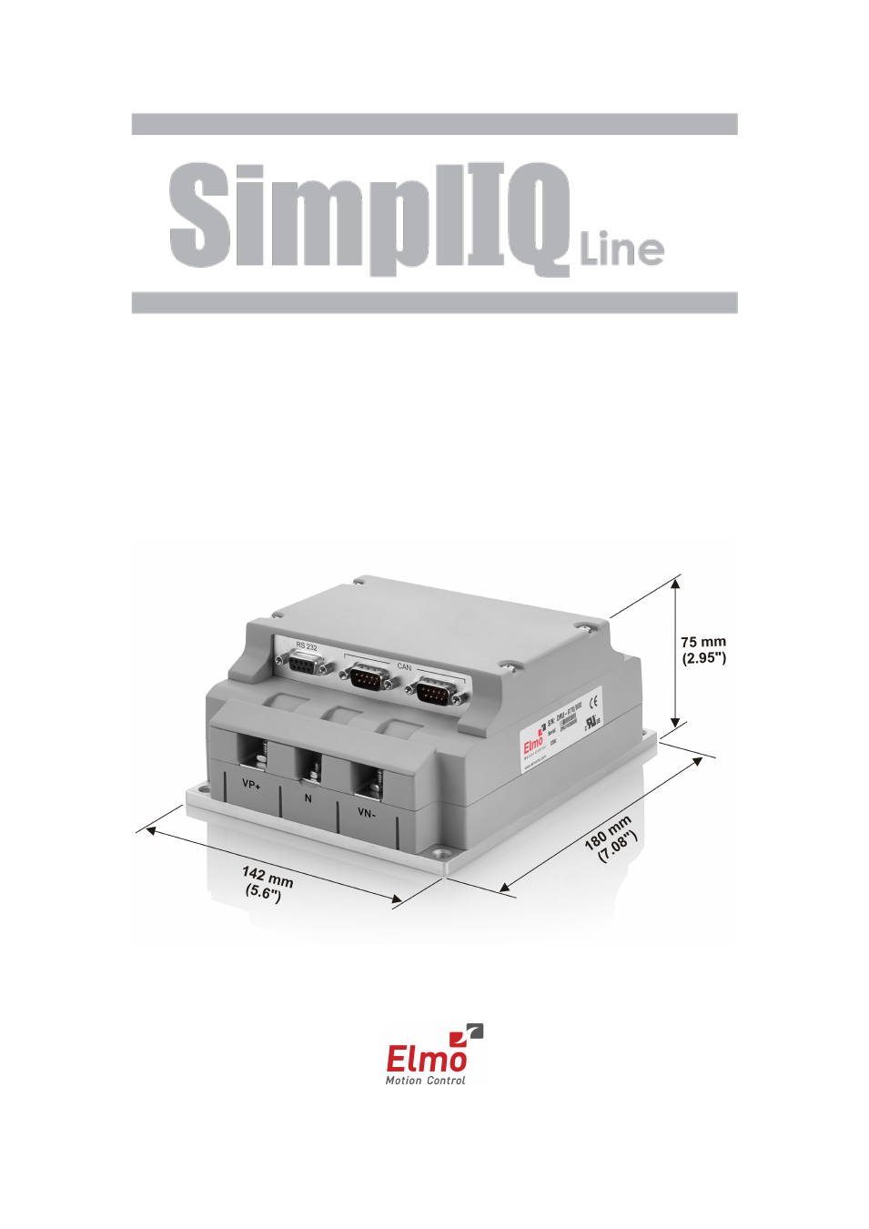
Table of contents
Document Outline
- Chapter 1: Safety Information
- Chapter 2: Product Description
- Chapter 3: Installation
- 3.1. Before You Begin
- 3.2. Unpacking the Drive Components
- 3.3. Connectors
- 3.4. Mounting the Drum HV (High Voltage)
- 3.5. Connecting the Cables
- 3.5.1. Wiring the Drum HV (High Voltage)
- 3.5.2. Connection Diagrams
- 3.5.3. Connecting the Power Cables
- 3.5.4. Connecting the Control and Backup Supply (24 V)
- 3.5.5. Feedback and Control Assemblies
- 3.5.6. Main Feedback Cable (FEEDBACK A)
- 3.5.7. Main and Auxiliary Feedback Combinations
- 3.5.8. Auxiliary Feedback (FEEDBACK B)
- 3.5.8.1. Main Encoder Buffered Outputs or Emulated Encoder Outputs Option on FEEDBACK B (YA[4]=4)
- 3.5.8.2. Differential Auxiliary Encoder Input Option on FEEDBACK B (YA[4]=2)
- 3.5.8.3. Single-Ended Auxiliary Input Option on FEEDBACK B (YA[4]=2)
- 3.5.8.4. Pulse-and-Direction Input Option on FEEDBACK B (YA[4]=0)
- 3.5.9. I/O Port
- 3.5.10. Communication Cables
- 3.6. Powering Up
- 3.7. Heat Dissipation
- 3.8. Initializing the System
- Chapter 4: Technical Specifications
- 4.1. Features
- 4.2. Dimensions
- 4.3. Power Ratings
- 4.4. Environmental Conditions
- 4.5. Control Specifications
- 4.6. Feedbacks
- 4.7. I/Os
- 4.8. Communications
- 4.9. Pulse-Width Modulation (PWM)
- 4.10. Compliance with Standards