90 0 mhz mod ul e – Elkhart Brass Scorpion RF 8294-07 User Manual
Page 10
10
Installation Step 3: RF Settings Setup
RF Receiver/Control Module Settings –
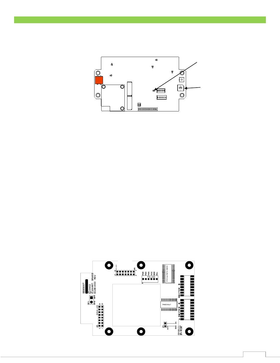
Remove the cover from the RF Receiver/Control Module. SW4 (see Figure 1) allows this board to be
used in different product applications. The firmware has been programmed such that the SW4 rotary
position has no effect on programming, so the dial should remain in position 1.
Figure 1: RF Receiver/Control Module Circuit Board
Handheld RF Controller Settings –
Remove the battery cover from the handheld RF controller. Remove the four (4) screws holding
the two halves of the cover together using a #1 size Pozidriv® screwdriver (use caution with a
standard Philips screwdriver as it may strip the screw heads).
Locate the security code switches on the circuit board (see Figure 2).
Change the switches to match the settings of the RF Receiver/Control Module except switch A
position 1. One incorrect setting will prevent the system from working properly.
Ensure the battery lead connector is securely fastened to the transmitter circuit board.
When reassembling the handheld controller, ensure that no wires will be pinched, close the
cover halves, and replace the screws. Do not exceed 6 in-lbs. of torque. The screws should be
just snug. Do not over tighten the screws or the plastic enclosure could strip.
With the monitor power on, turn on the handheld controller. The PWR/XMIT light will flash.
Once the flashing light stops (light will be off), turn the handheld on once again. This can take
3-5 minutes and is required to sync the handheld to the monitor. The handheld is now ready for
use.
Figure 2: Handheld RF Controller Circuit Board
DS5
DS2
B
A
DS1
SW4
SW1
DS4
P2
DS3
P3
DS6
P1
P4
SW2
SW3
Status LED
SW4
Swi
tc
h A
Swi
tc
h B
Secu
rity
Switche
s
Extern
al
Co
n
ne
ctor
90
0 MHz
Mod
ul
e