Important – Elkhart Brass Scorpion 7400 EXM Monitor User Manual
Page 14
14
1
2
1
2
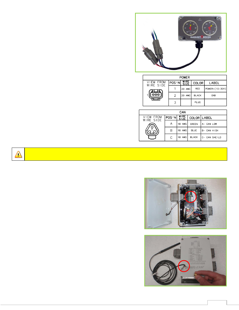
Position Feedback Display –
Using the Position Display template shown in the
Component Mounting Templates section, drill the
two 11/64” holes shown through the panel
intended for mounting the display.
Mount the Position Feedback Display using two
(2) 6-32 x ½” fasteners secured with blue Loctite
242 or equivalent. Torque to 50-60 in-lbs.
Connect plug 2 leads to the appropriate CAN
line.
Supply power to the Position Feedback Display by
connecting plug 1 leads to an appropriate power
source.
Install a 1 Amp fuse into the positive power lead
of the Position Feedback Display for a 12V system
(1/2 Amp for 24V system).
Refer to the respective figures for information on
the plugs’ pins.
Important:
Ensure horizontal & vertical calibration is correct or display may not
accurately show position. See Installation Step 3: Calibrate the EXM System.
External RF Antenna Module –
Remove the OEM Interface Module cover and
connect its antenna wire (under cover) to the round,
white connection on the RF Transceiver Module.
Replace the OEM cover.
Remove the protective cover from the antenna mount
on the OEM cover and install & tighten the end of
the antenna harness without the antenna onto the
coax connector.
Locate a suitable mounting surface that provides the
most unobstructed line of sight to the monitor’s
antenna. Drill a ¼” hole in a suitable mounting
surface for the antenna. Unscrew the antenna from
the harness and use its lock washer and nut to attach
the antenna mount to the hole.