Elkhart Brass Scorpion 7400 EXM Monitor User Manual
Page 11
11
1
2
1
2
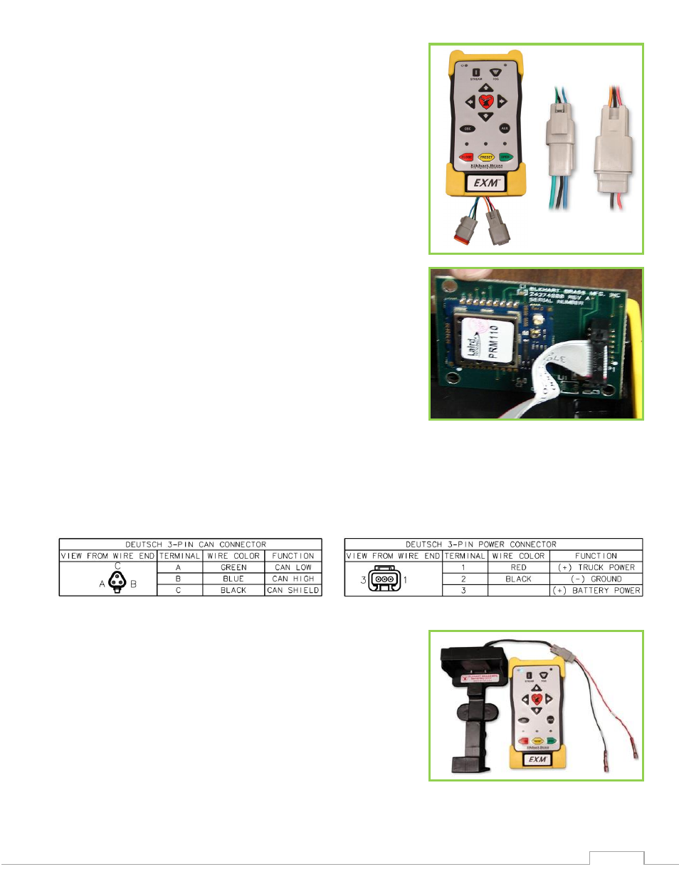
RF Transceiver in Panel Mount
1
2
Panel Mount Controller -
Using the Panel Mount Controller template in the
Component Mounting Templates section, drill any 4 of
the 7/32” holes shown through the panel intended to
hold the Panel Mount.
Mount the controller with four (4) 10-24 x ½” screws
using blue Loctite 242 or equivalent. Screw length
should provide 0.187”-0.25” thread engagement into
panel mount. Torque screws to 50-60 in-lbs.
If the Panel Mount will use the CAN line to communicate
with the other EXM components, connect plug 1 leads to
the appropriate CAN line.
If the Panel Mount will use RF communication, install the
RF Transceiver Module into the controller.
o
Remove the back cover from the Panel Mount
Controller using a flathead screwdriver.
o
Connect the RF Transceiver with the wires running the
length of the board as shown in the picture to the right.
o
Reattach the back cover of the Panel Mount. Ensure no
wires are pinched.
o
If the CAN leads will not be used, replace wires with
appropriate plugs.
Supply power to the controller by connecting plug 2 leads to an appropriate power source.
Install a 1 Amp fuse into the positive power lead for a 12V system (1/2 Amp for 24V system).
Refer to the respective plug figures for information on the plugs’ pins.
Handheld Controller and Docking Station –
Using the Docking Station template shown in the
Component Mounting Templates section, drill all 7/32”
holes shown through the panel intended for mounting
the Docking Station.
Mount the Docking Station with the supplied 10-24 x
3/8” screws using blue Loctite 242 or equivalent.
Torque screws to 50-60 in-lbs. The screw length allows
for a panel thickness range of 0.046”-0.125”.
Supply power to the Docking Station by connecting the plug leads shown to an appropriate
unswitched power source.