Installation, Wiring requirements – Det-Tronics X3300 Protect-IR Multispectrum IR Flame Detector User Manual
Page 6
INSTALLATION
DETECTOR POSITIONING
Detectors should be positioned to provide the best
unobstructed view of the area to be protected. The
following factors should also be taken into consideration:
• Identify all high risk fire ignition sources.
• Be sure that enough detectors are used to adequately
cover the hazardous area.
• Locate and position the detector so that the fire
hazard(s) are within both the field of view and
detection range of the device. Refer to Appendix A
for specific information.
• Be sure that the unit is easily accessible for cleaning
and other periodic servicing.
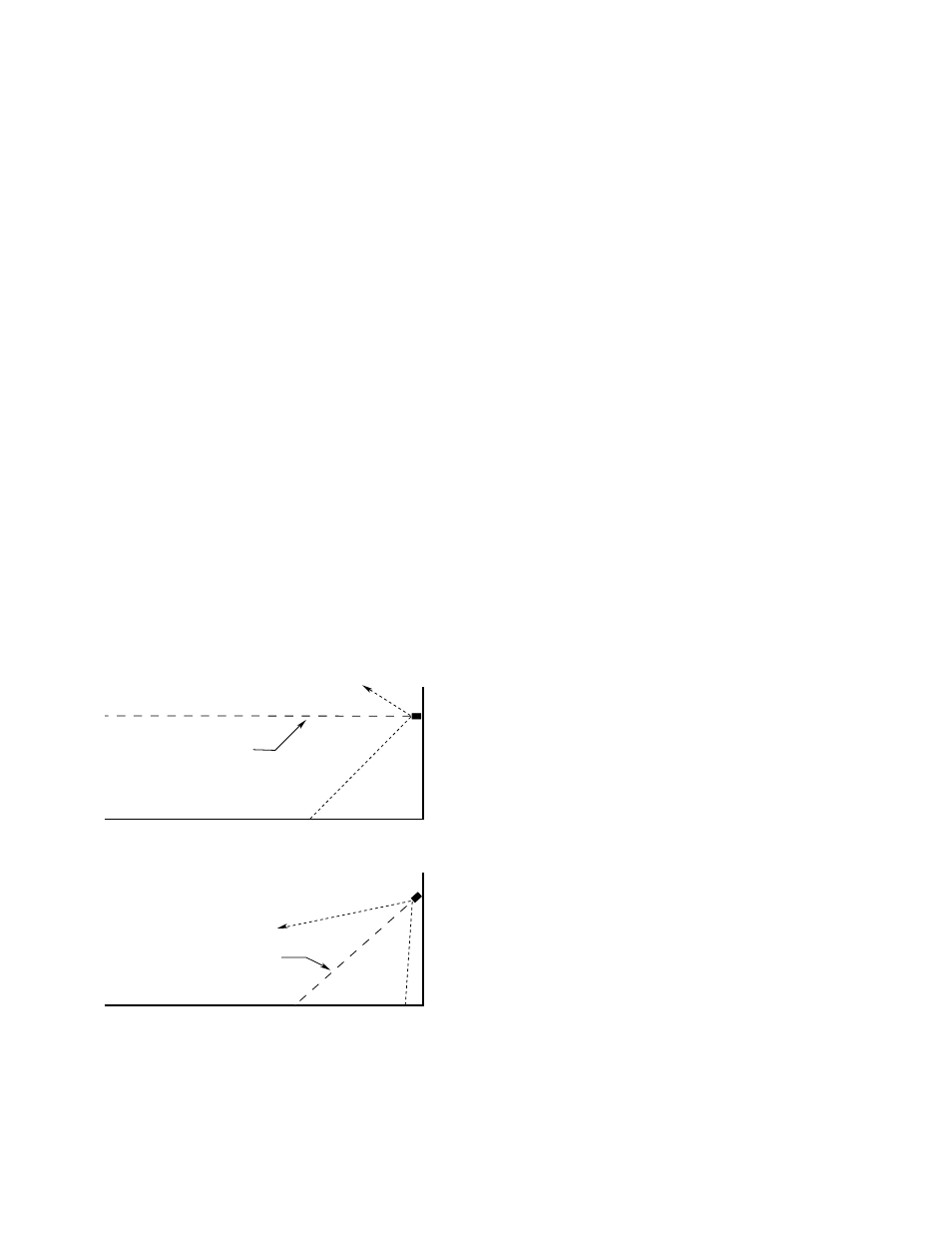
• For outdoor applications, the detector should be
aimed downward at least 10 to 20 degrees to allow
lens openings to drain. See Figure 1. The detector
should be positioned so that its field of view does not
cover areas outside the hazardous area. This will
minimize the possibility of false alarms caused by
activities outside the area requiring protection.
• For best performance, the detector should be
mounted on a rigid surface in a low vibration area.
• Dense fog, rain or ice can absorb IR radiation and
reduce the sensitivity of the detector.
• Although IR detectors are less affected by smoke than
other detectors, the X3300 should not be placed
where rising combustion products can obscure its
vision. If smoke is expected before fire, smoke or
other alternative detectors should be used in
conjunction with the X3300. For indoor applications, if
dense smoke is expected to accumulate at the onset
of a fire, mount the detector on a side wall at least a
few feet (approximately 1 meter) down from the
ceiling.
• If possible, fire tests should be conducted to verify
correct detector positioning and coverage.
WIRING REQUIREMENTS
WIRE SIZE AND TYPE
The system should be wired using a 14 to 22 gauge (1.3
to 0.5 mm2) cable. The wire size selected should be
based on the number of detectors connected, the
supply voltage and the cable length. A minimum input
voltage of 18 vdc must be present at the X3300.
The use of shielded cable is recommended to protect
against interference caused by EMI and RFI. When
using cables with shields, terminate the shields as
shown in Figures 7 through 10. Consult the factory if not
using shielded cable.
In applications where the wiring cable is installed in
conduit, the conduit should not be used for wiring to
other electrical equipment.
CAUTION
Installation of the detector and wiring should be
performed only by qualified personnel.
PROTECTION AGAINST MOISTURE DAMAGE
It is important to take proper precautions during
installation to ensure that moisture will not come in
contact with the electrical connections or components
of the system. The wiring pigtail for the X3300 is factory
sealed for easy installation onto a junction box where
electrical connections are made. The integrity of the
system regarding moisture protection must be
maintained for proper operation and is the responsibility
of the installer.
If conduit is used, drains must be installed at water
collection points to automatically drain accumulated
moisture. Conduit breathers should be installed at
upper locations to provide ventilation and allow water
vapor to escape. At least one breather should be used
with each drain.
4
Figure 1—Detector Orientation Relative to Horizon
CENTER AXIS
OF DETECTOR
FIELD OF VIEW
CENTER AXIS
OF DETECTOR
FIELD OF VIEW
INCORRECT
CORRECT
NOTE: DETECTOR MUST ALWAYS BE AIMED
DOWNWARD AT LEAST 10 TO 20 DEGREES.
B1974