Installation – Det-Tronics X3301 Multispectrum IR Flame Detector with Pulse Output User Manual
Page 7
5
95-8528
11.1
INSTallaTION
NOTE
The recommended lubricant for threads and
O-rings is a silicone free grease (p/n 005003-
001) available from Det-Tronics. Under no
circumstances should a lubricant containing
silicone be used.
DETECTOR pOSITIONINg
Detectors should be positioned to provide the best
unobstructed view of the area to be protected. The
following factors should also be taken into consideration:
• Identify all high risk fire ignition sources.
• Be sure that enough detectors are used to adequately
cover the hazardous area.
• Be sure that the unit is easily accessible for cleaning
and other periodic servicing.
• Verify that all detectors in the system are properly
located and positioned so that any fire hazards are
within both the Field of View (FOV) and detection
range of the detector. The Q1201C Laser Aimer
is recommended for establishing the detector’s
FOV. Refer to Appendix A for specific information
regarding detector range and FOV.
• The detector should be aimed downward at least 10
to 20 degrees to allow lens openings to drain. See
Figure 1. The detector should be positioned so
that its FOv does not cover areas outside the
hazardous area.
This will minimize the possibility
of false alarms caused by activities outside the area
requiring protection.
• The detector must be mounted on a rigid surface in
a low vibration area.
• Dense fog, rain or ice can absorb IR radiation and
reduce the sensitivity of the detector. To ensure
optimum performance, be certain that the internal
optical heater is enabled on detectors that are used
in applications where snow, ice, and/condensation
are likely to occur.
• Although IR detectors are less affected by smoke
than other detectors, the X3301 should not be placed
where rising combustion products can obscure
its vision. If smoke is expected before fire, smoke
or other alternative detectors should be used in
conjunction with the X3301. For indoor applications,
if dense smoke is expected to accumulate at the
onset of a fire, mount the detector on a side wall at
least a few feet (approximately 1 meter) down from
the ceiling.
• If possible, fire tests can be conducted to verify
correct detector positioning and coverage.
• For ATEX installations, the X3301 Flame Detector
housing must be electrically connected to earth
ground.
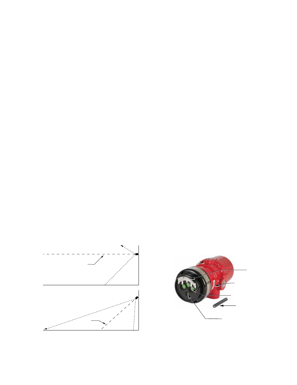
DETECTOR ORIENTaTION
Refer to Figure 2 and ensure that the
oi
plate will be
oriented as shown when the X3301 is mounted and
sighted. This will ensure proper operation of the
oi
system and will also minimize the accumulation of
moisture and contaminants between the
oi
plate and the
viewing windows.
Important
If removed, the
oi
plate must be securely
tightened to ensure proper operation of the
oi
system (40 oz./inches [28.2 N .cm] recommended).
figure 1—Detector Orientation Relative to Horizon
CENTER AXIS
OF DETECTOR
FIELD OF VIEW
CENTER AXIS
OF DETECTOR
FIELD OF VIEW
INCORRECT
CORRECT
NOTE: DETECTOR MUST ALWAYS BE AIMED
DOWNWARD AT LEAST 10 TO 20 DEGREES.
D1974
VIEWING WINDOW (3)
oi PLATE
PLACE MAGNET
HERE TO INITIATE
MAGNETIC
oi
oi MAGNET
DETECTOR
STATUS INDICATOR
F2068
figure 2—front View of the X3301