Det-Tronics X9800 IR Flame Detector with Pulse Output User Manual
Page 10
95-8555
5.1
8
Figures 11 and 12 provide examples of typical
installations with a X9800 wired to a fire alarm
panel.
Figure 13 shows an EOL resistor installed within the
integral wiring compartment of the detector (refer to
“EOL Resistors” for details).
2. Check all field wiring to be sure that the proper
connections have been made.
Important
Do not test any wiring connected to the detector
with a meg-ohmmeter. Disconnect wiring at
the detector before checking system wiring for
continuity.
3. Make the final sighting adjustments and use a 14
mm hex wrench to ensure that the mounting arm
assembly is tight.
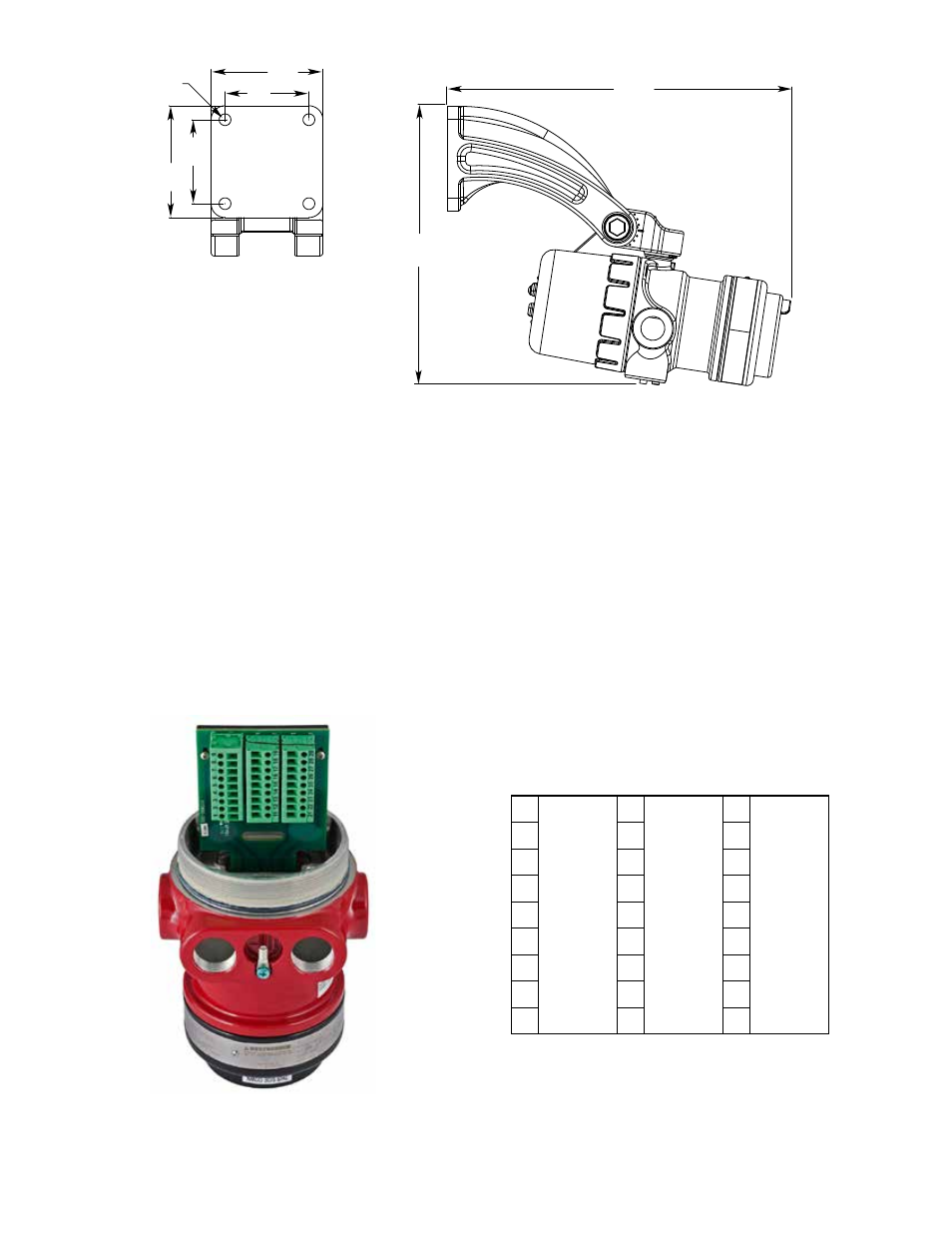
13.1
(33.4)
10.6
(27.0)
4.0
(10.2)
4.0
(10.2)
3.0
(7.6)
3.0
(7.6)
4X ø0.42
(1.1)
E2069
NOTE: THIS ILLUSTRATION SHOWS THE
DETECTOR MOUNTED AT THE 10° MINIMUM.
THESE DIMENSIONS WILL CHANGE BASED
ON THE DETECTOR’S MOUNTING ANGLE.
Figure 3—Q9033 mounting arm without Collar attachment Dimensions in Inches (cm)
(See Figure 1 for Correct Detector Orientation.)
Figure 5—X9800 Pulse Wiring Terminal Identification
Figure 4—X9800 Terminal block
9
8
7
6
5
4
3
2
1
19
18
17
16
15
14
13
12
11
PULSE OUT
COM FIRE
COM FIRE
N.O. FIRE
N.O. FIRE
N.C. FIRE
N.C. FIRE
COM FAULT
COM FAULT
N.O. FAULT
N.O. FAULT
24 VDC +
24 VDC +
24 VDC –
24 VDC –
24 VDC –
29
28
27
26
25
24
23
22
21
SPARE
SPARE
RS-485 A
RS-485 B
MAN
Oi
B2070