Step 5 installation of diverter and thumb screw, Step 7 installation of riser and cover, Step 4 installation of slot covers – Clarus Environmental Tru-Flow Splitter System User Manual
Page 3
3
© Copyright 2011. All rights reserved.
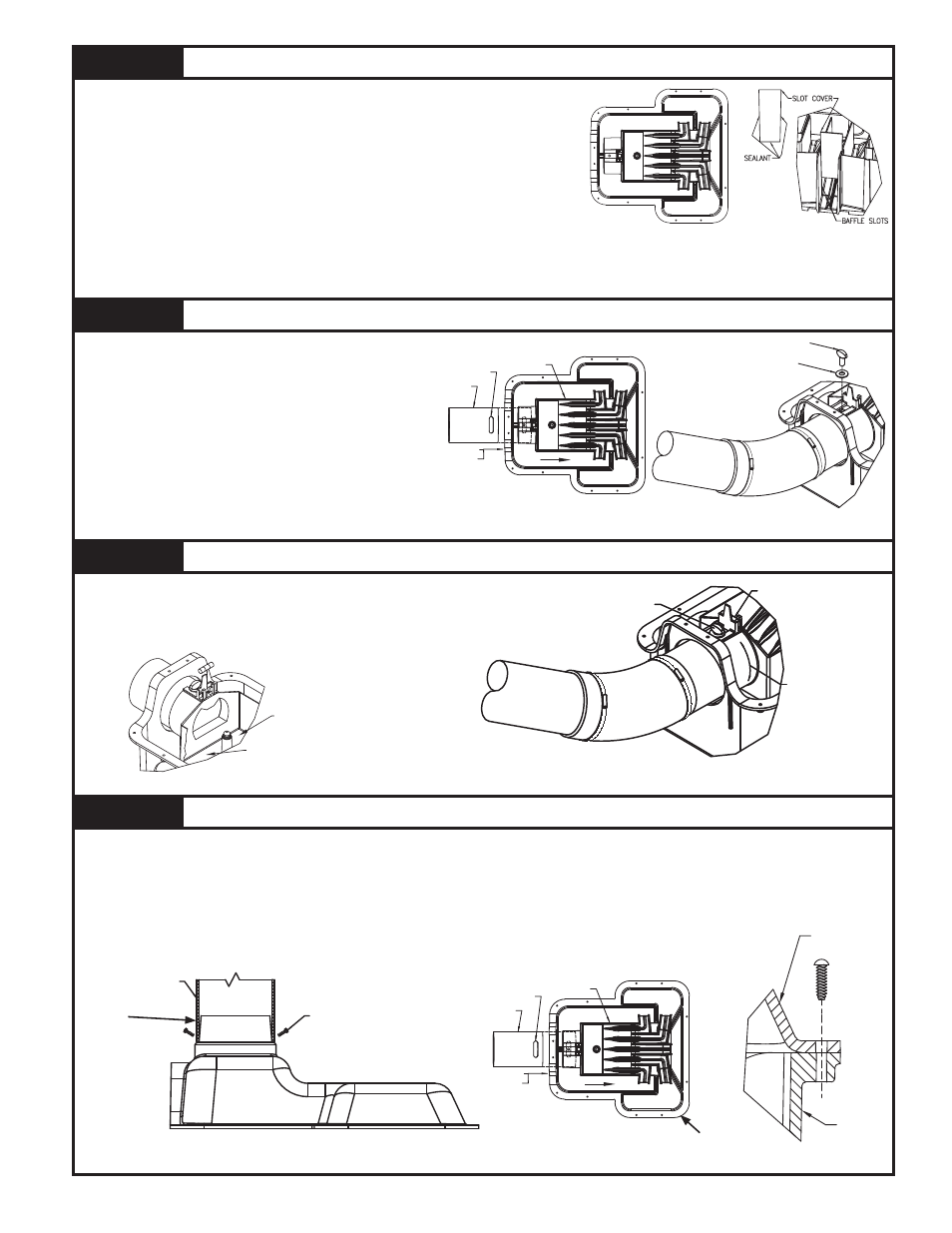
STEP 5
Installation of Diverter and Thumb Screw
5.1) Set diverter into place and insert slotted pipe
nipple into the diverter. See Figure 5.1.
5.2) Engage 3/8"-16 thumb screw and large washer
onto the diverter as shown in figure 5.2. DO
NOT OVERTIGHTEN THUMB SCREW.
5.3) Slide diverter and slotted pipe nipple as far
forward as possible, see arrow in Figure
5.1.
5.4) Tighten rubber coupling, which connects inlet
pipe and slotted pipe nipple.
Figure 5.1
Figure 5.2
STEP 6
Installation of Level and Initial Adjustment
6.1) Snap level into the diverter. See Figure 6.1.
6.2) Level the diverter by use of the thumb screw and tap the bottom surface
of the diverter at “A” & “B” see Figure 6.1.
See Figure 6.2. DO NOT OVER TIGHTEN THUMB SCREW.
Figure 6.2
STEP 7
Installation of Riser and Cover
7.1)
Apply ample amounts of RTV Silicone to outside of SCH40 or SDR35 pipe (supplied by others).
7.2) Attach riser pipe SCH40 or SDR35 (supplied by others) to cover as shown in Figure 7.1.
7.3)
Place an ample coating of RTV Silicone around the basin lip to form a gasket.
7.4) Place cover onto basin, then attach washers and screws as shown in Figure 7.2. Repeat where necessary.
7.5) Fill in dirt around splitter system, necessary pipes, connections, risers, and trenches.
Note: Assure riser opening is capped to prevent debris from entering the splitter system. Do not glue cap.
Flag location of splitter system riser to prevent damage.
Figure 7.1
Figure 7.2
SK1947
SK1948
SK1951
SK1952
Note: Do not over tighten screws.
STEP 4
Installation of Slot Covers
4.1) Determine the required number of slot covers from Figure 1.1 and the
required baffle slot for each slot cover. See Figure 4.1.
4.2) Blank slot covers should be installed in the baffle slot openings of 2,3
and 4 if their corresponding cutouts are not to be used for trench pipes.
See Figure 1.1 and 4.1. When cutouts 2 and/or 3 and/or 4 are used and
the splitter system is being pumped to, these baffle slots must have slot
covers with the restrictor opening installed.
4.3)
Apply RTV Silicone or PVC cement to the bottom and sides of the
necessary slot cover. See Figure 4.2.
4.4) Place slot cover into baffle slot.
Apply additional RTV Silicon or PVC
cement as needed along edges. See Figure 4.2. Repeat steps 4.3 & 4.4
for each required slot cover.
Note: Assure each required slot cover is sealed to prevent leakage into D-Box basin.
Figure 4.2
1
2
3
4
5
SK1945
SK1946
Figure 4.1
SLOTTED
PIPE NIPPLE
DIVERTER
CONNECT
SLOT
THUMB SCREW
WASHER
"A"
"B"
SK1949
Figure 6.1
ADJUST DIVERTER ROTATION
SEE STEP 6.2
ADJUST TIGHTNESS
BY USE OF
THUMB SCREW
LEVELING DEVICE
SK1950
SCREWS
PIPE (SUPPLIED BY OTHERS)
BASIN
LID
SLOTTED
PIPE NIPPLE
DIVERTER
CONNECT
SLOT
SK1947
Apply RTV
Silicone
Apply RTV
Silicone