Step 1 splitter system outlets, Step 3 installation of assembled basin – Clarus Environmental Tru-Flow Splitter System User Manual
Page 2
2
© Copyright 2011. All rights reserved.
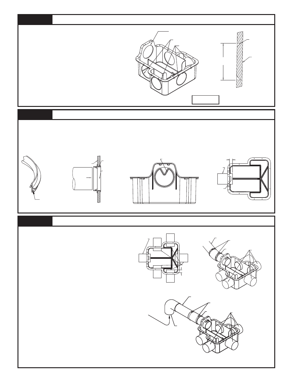
STEP 1
Splitter System Outlets
1.1) Determine the number of outlets to be used on
the splitter system based on the layout of the
trench field. When pumping to the splitter system,
optimum results are obtained if:
a.) Installations requiring 4 slot openings/trench
lines utilize slot openings 1,2,4, & 5.
b.) Installations requiring 3 slot openings/trench
lines utilize slot openings 1,3, & 5.
1.2) Score and cut through with a knife at the bottom of
v-groove. If required score several times around and
cut through.
DO NOT HIT WITH A HAMMER.
1.3) Trim and clean the diameter of the hole, leaving it
the same as the molded diameter.
DO NOT OVER
TRIM DIAMETER. Refer to Figure 2.2
STEP 2
Installation of Pipe Seals and Slotted Pipe Nipple
Splitter system is supplied with pipe seals for 4" SDR35 pipe. If using 4" SCH40 pipe, order P/N 173-0006.
2.1) Apply sealant around mating surface of pipe seal as shown in Figure 2.1. Repeat for each required pipe seal.
2.2) Place pipe seals in necessary holes as shown in Figure 2.2 & Figure 2.3.
2.3) Insert slotted pipe nipple through the inlet hole and pipe seal, pushing through about ¾". See Figure 2.4.
Note: Assure the slot end of the pipe nipple is inside the basin and the slot is facing upward and centered.
Figure 2.1
Figure 2.3
STEP 3
Installation of Assembled Basin
3.1) Set basin into place.
3.2) Insert necessary trench pipes into basin, pushing
through approximately 1½". See Figure 3.1. The
number of pipes varies for each installation.
3.3) Connect the inlet pipe to slotted pipe nipple with a
coupling (flexible rubbers shown). Do not tighten
coupling at this time. If used see Figure 3.2.
3.4) Installations in which the splitter system will be pumped
to are required to have at least a 3' length of 4" PVC
and a 4" elbow connected to the slotted pipe nipple.
See Figure 3.3 for required positioning of elbow. This
piping configuration will promote smooth uniform flow.
The piping from the pump to the elbow should be
sized based on the pump discharge. Use bushings/
reducers as necessary to connect to the elbow.
3.5) Maximum flow through the splitter system is dependent
on the number of trench pipe openings.
The splitter
system can handle 30 gpm with 5 openings, 21
gpm with 4 openings, 17 gpm with 3 openings
and 13 gpm with 2 openings.
Note: Assure slot in pipe nipple is centered and facing upward
when connecting coupling or PVC.
Note: Basin must be leveled at this time in both
directions.
Note: The splitter system must sit level on undisturbed ground
or on packed sand or gravel before backfilling.
SK1941
Figure 2.2
Figure 2.4
SK1942
Figure 1.2
SK1956
SK1944
Figure 3.2
SK1943
Figure 3.1
SK2100
Figure 3.3
Patent No. 6,112,766
and 6,152,650
INLET HOLE
(DO NOT USE FOR OUTLET)
POSSIBLE CUTOUTS
MOLDED IN HOLES
SK1939
Figure 1.1
BOTTOM OF
V-GROOVE
BASIN WALL
MOLDED
DIAMETER
SK1973
MATING
SURFACE
SK1940
PIPE
DIRECTION
OUTSIDE OF
BASIN WALL
PIPE SEAL
DO NOT OVER
TRIM KNOCK-OUTS
BUCKLE SEAL TO INSERT.
3/4"
SLOTTED
PIPE NIPPLE
SLOT
SLOTTED
PIPE NIPPLE
OUTLET PIPES
1 1/2
SEPTIC TANK
OUTLET PIPE
COUPLING, RUBBER
(SHOWN) OR PVC
(SUPPLIED BY OTHERS)
DO NOT TIGHTEN
FOR THIS STEP
NUMBER OF TRENCH
PIPES VARIES FOR
EACH INSTALLATION.
4" PVC PIPE
MINIMUM 3' LENGTH
COUPLING, RUBBER
(SHOWN) OR PVC
(SUPPLIED BY OTHERS)
DO NOT TIGHTEN
FOR THIS STEP
NUMBER OF TRENCH
PIPES VARIES FOR
EACH INSTALLATION.
4" PVC ELBOW
ORIENTATION AS
SHOWN.
PUMPED EFFLUENT