Prepare site • assemble burner • mount burner, Inspect/repair/replace vent system, Combustion/ventilation air openings – Carlin EZ-1/2/3 User Manual
Page 5
Carlin part number MNEZ123 Rev. 07/13/11
– 5 –
Model EZ-1/2/3 oil burners — Instruction manual
2. Prepare site • assemble burner • mount burner
Inspect/repair/replace vent system
Do not install this burner unless you have verified the entire
vent system and the appliance are in good condition and
comply with all applicable codes. And ...
The vent and chimney must be sized and constructed in
accordance with all applicable codes.
Do not install or use an existing manual damper in the breech-
ing (vent connector) or chimney.
Do not connect the appliance vent connector to a chimney
or vent serving a fireplace, incinerator or solid-fuel-burning
apparatus.
In a cold climate, do not vent into a masonry chimney that
has one or more sides exposed to the outside. Install a listed
stainless steel liner to vent the flue products.
A defective vent system could result in severe personal injury,
death or substantial property damage.
Prepare vent/chimney
• Secure all metal vent joints with screws, following the vent manufac-
turer’s instructions. Seal all joints in the vent system and chimney.
Repair masonry chimney lining and repair all mortar joints as needed.
• Install a barometric draft regulator in the vent piping if specified in the
appliance manual. (The damper must be located in the same space
as the appliance.)
• Provide support for the vent piping. Do not rest the weight of any of the
vent piping on the appliance flue outlet.
Combustion/ventilation air openings
Even if combustion air is piped to an (optional) burner
air intake adapter, the boiler room must still have the
minimum air openings listed in Table 2 and described in the
following paragraphs. This is to provide needed ventilation to
keep the burner and appliance cool and to avoid the boiler
room developing negative pressure.
The combustion air openings MUST be sized based on the
total input of
all appliances in the room.
Check appliance manual and applicable codes for required sizing/design/
placement of combustion/ventilation air openings. You can use the follow-
ing general guidelines, taken from NFPA 31, provided they meet all local
requirements.
Louvers/screens
• Air opening sizes are always given in free area. This means after de-
duction for louver obstruction. If you can’t find the louver reduction for
the grilles used, assume free area is 20% of total for wood louvers, or
60% of total for metal louvers.
• Screens can be no finer than ¼-inch mesh, and must be accessible
for cleaning.
Residential installations
Unconfined spaces (at least 7,000 cubic feet per GPH)
• An unconfined space means a room with at least 7,000 cubic feet vol-
ume for each GPH input (or 50 cubic feet per MBH) of
all appliances
in the room. Example: For each 1 GPH oil input, the room must have
7,000 cubic feet (875 square feet with an 8-foot ceiling height.)
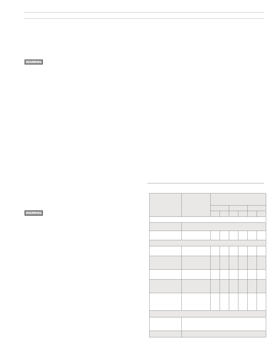
Table 2
Minimum combustion/ventilation air openings
• Open basements and crawl spaces are usually large enough, and will
generally allow enough air infiltration so special provisions will seldom
be required.
• If the building is tightly constructed, you will have to provide outside
air openings into the building. The total free area of the openings must
be at least 1 square inch per 5,000 Btuh (28 square inches per GPH)
of all appliances in the space.
• See Table 2 for summary.
Air openings to confined spaces
(less than 7,000 cubic feet per GPH)
• Air taken from inside building only —
• Provide two openings — one near floor, the other near ceiling. Provide
free area of 140 square inches per GPH input. If building is tightly
constructed, provide air opening(s) into building providing 30 square
inches per GPH as well.
• Air taken from outside —
• Direct through outside wall or vertical ducts: Provide two openings — one
near floor, the other near ceiling. Provide free area of 35 square inches
per GPH input.
• Through horizontal ducts: Provide two openings — one near floor, the other
near ceiling. Provide free area of 70 square inches per GPH input.
• Ventilation air from inside/combustion air from outside
Size openings to interior to provide 140 square inches free area per GPH input.
Size outside air duct to provide 28 square inches free area per GPH.
• See Table 2 for summary.
Source
of air
Mininimum
free area
of opening(s)
Total grill area, typical (sq. in.)
for firing rates of:
1 GPH
2 GPH
3 GPH
Wood Metal Wood Metal Wood Metal
Residential installations, unconfined spaces (7,000 cu. ft. volume per GPH)
From inside building,
typical construction
No special openings required if natural infiltriation is sufficient.
From inside building,
tight construction
1 or more grilles
30 Sq. in./ GPH
150
50
300
100
450
150
Residential installations, confined spaces
From inside building
through interior walls
2 openings, each
140 Sq. in./ GPH
700
234 1400 467 2100 700
From outside building
direct through outside
wall
2 openings, each
35 Sq. In./ GPH
175
59
350
117
525
175
From outside building
through vertical ducts
2 openings, each
35 Sq. In./ GPH
175
59
350
117
525
175
From outside building
through horizontal
ducts
2 openings, each
70 Sq. In./ GPH
350
117
700
234 1050 350
Ventilation through
interior walls, with an
opening to outside
2 Int. openings,
each
140 Sq. In./ GPH
1 Exterior opening
28 Sq. In./ GPH
700
140
234
47
1400
280
467
94
2100
420
700
140
Commercial installations
From outside building
direct through adjacent
outside wall
One opening through outside wall, providing free area of at least
28 Square inches per GPH input
Other conditions
Size openings per local codes/jurisdictions