Prepare burner, Install head positioning bar, Adjust air band (initial setting) – Carlin EZ-1/2/3 User Manual
Page 11
Carlin part number MNEZ123 Rev. 07/13/11
– 11 –
Model EZ-1/2/3 oil burners — Instruction manual
3. Prepare burner
(continued)
4. Replace the retention ring assembly by slipping one of the riveted arms
through the gap between the electrode tips. Align this arm straight up,
with the ring clamp firmly against the nozzle adapter shoulder. Then
tighten the clamping screw.
5. Check the electrode settings. Position the electrodes as shown in Fig-
ure 7. These settings are critical in ensuring a reliable ignition. Once
the electrodes are set, check all clamps to be sure they are securely
tightened.
Figure 8 Carefully support the nozzle adapter when
removing or installing nozzle
Install head positioning bar
1. The burner is supplied with up to seven calibrated bars that properly
position the head in the air tube. See the table below for head position-
ing bars available.
2. The head positioning bars are stamped with a nozzle size range. Use a
positioning bar with the range that includes the nozzle size installed.
3. See Figure 9. Remove the existing bar (if installed) and replace with
the correct one.
4. Store any remaining bars in the rear of the burner to allow future
change, if needed.
Model
Range
Head positioning bars available
EZ-1
EZ-1-HP
0.50 – 1.65
GPH
7 options:
0.50 / 0.60-0.65 / 0.75
0.85-1.00 / 1.10-1.25 /
1.10-1.25 / 1.35-1.50 / 1.65
EZ-2
EZ-2-HP
1.50 – 2.25
GPH
4 options:
1.50 / 1.65-1.75
2.00 / 2.25
EZ-3
EZ-3-HP
2.00 – 2.50
GPH
3 options:
2.00 / 2.25 / 2.50
Adjust air band (initial setting)
1. The burner pump pressure is factory set. The pump pressure is indi-
cated on a label affixed to the pump only if it is something other than
100 psi. The air band divisions match the nozzle size regardless of the
pump pressure setting. Loosen the lock screw and move the air band
until the pointers line up with the setting indicated in the OEM Set-up
Table or to a setting that matches the nozzle size (for a retrofit burner).
See figure 10.
2. NOTE: For high altitude installations above 2,000 feet, increase the
air supply setting 4% for each 1,000 feet above 2,000 feet above sea
level.
3. The burner is now adjusted to the approximate air band setting for the
nozzle size indicated. When you check combustion with instruments
during start-up or servicing, you may have to adjust the air band slightly
to achieve the desired combustion readings. See “Adjust burner using
test instruments,” page 22.
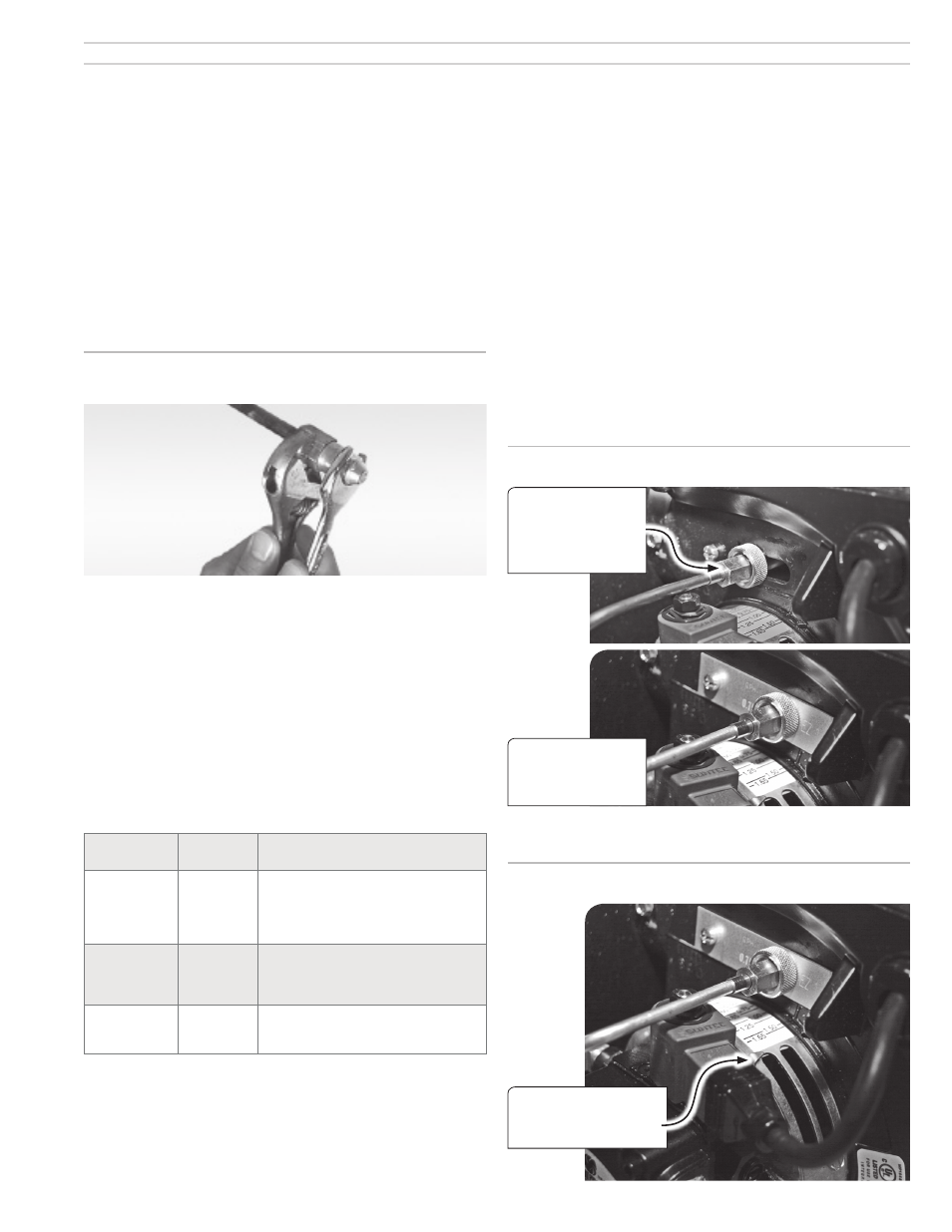
Figure 9 Installing head positioning bar
Remove head bar
retaining screw and
disconnect oil line and
knurled nut from nozzle
line.
Install the head bar
with the correct firing
nozzle size range for
the application.
Figure 10 Initial setting of air band
Initially set air band so the
pointer points at the burner
nozzle size.