Circuit details – Carbolite TZF Series User Manual
Page 13
MF12 3.12
13
7.0 C
IRCUIT
D
ETAILS
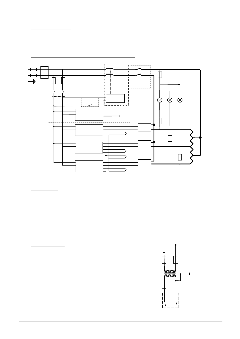
Safety Switches type A: a 2-pole Heater Switch is fitted directly in the element circuit in models
up to 16A rating.
Safety Switch type B: a Heater Switch is fitted into the contactor coil circuit in models over 16A.
7.1 Single Phase (example for TZF, control method A)
7.2 2- or 3-Phase
See also section Error! Reference source not found.. for certain models.
Each SSR is connected to a different phase. The control circuit is taken between L1 and N.
Safety switch A applies for 2-phase. Safety switch B applies for 3-phase.
If type F1 fuse is present, one per phase if fitted. If type F2 fuse is present, one is fitted; if type F3
fuse is present, one per phase is fitted.
Note that on 2- or 3-phase models there may be three separate neutrals taken to a common supply
terminal, depending on EMC filter requirements.
7.3 Higher Voltages
For 254V or above (or 440V, 3-phase) an isolating transformer is
fitted in the control circuit after the F2 fuses.
Instrument Switch
coil
slave
controller
thermocouples
overtemp.
controller
thermocouple
safety
switch B
SSR
heat
on
safety
switches A
F3
F1
F2
F3
N
L
PE
Filter (if fitted)
contactor
if fitted
if fitted
master
controller
SSR
SSR
slave
controller
F3
F3
main
ref.
slave
slave
+
+
+
–
–
–
F2
F2
Transformer
Instrument Switch