Installation – Carbolite CF 15 - CF 60 User Manual
Page 4
4
MF28 3.08
2.0 I
NSTALLATION
2.1 Unpacking & Handling
Lift the furnace or its component sections by the base: do not apply any force to the door or to
other protruding parts. Ensure that there are adequate lifting facilities before commencing.
Remove any packing material from the door gear and furnace chamber before use.
NOTE: This product contains Refractory Ceramic Fibre (better described as Alumino Silicate
Wool) for precautions and advice in handling this material see the ‘Repairs and Replacements’
section.
2.2 Split Model CF 24 or above (if ordered)
When transported as two components, connect them as follows. Remove the side panels from the
top and the left-hand side from the base. Remove the four fixing bolts from the top of the base.
Place the top onto the base, with the door above the control panel, and bolt the two halves
together.
Connect the thermocouple comp. cables to the appropriate terminal blocks. There are two such
cables, or three if chamber overtemperature control is fitted. The blocks and cables are labelled
(e.g. 1, 2 , 3).
Connect the door switch wire pair to the terminal block near the
door mechanism.
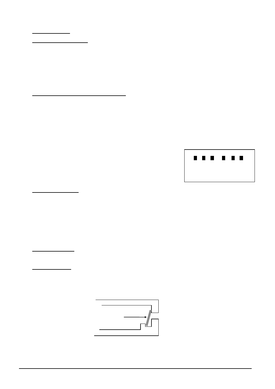
Connect the power cables to the terminal blocks below the lower
element holes. Because of different power supplies and national
standards, the details may differ from the details shown, or the
terminals may be in reverse order.
2.3 Siting & Setting Up
Place the furnace in a well ventilated room, away from other sources of heat, and on a floor or
surface which is resistant to accidental spillage of hot materials.
Do not place the furnace on an
inflammable surface.
Ensure that there is free space around the furnace.
Do not obstruct any of the vents in the control
section: they are needed to keep the controls cool.
Ensure that the furnace is placed in such a way that it can be quickly switched off or disconnected
from the electrical supply - see below.
2.4 Heating Elements
These are very fragile and are supplied separately. Please see the fitting instructions in section 5.6.
2.5 Baffle (optional)
Not CF 60
The baffle, a refractory tile, may be fitted if required. It should be carefully placed at the back of
the furnace chamber, as shown.
baffle
L1
L2
L3
N
N
N
cable colours: L: black
N: blue