Circuit diagrams – Carbolite CF 15 - CF 60 User Manual
Page 15
MF28 3.08
15
7.0 C
IRCUIT
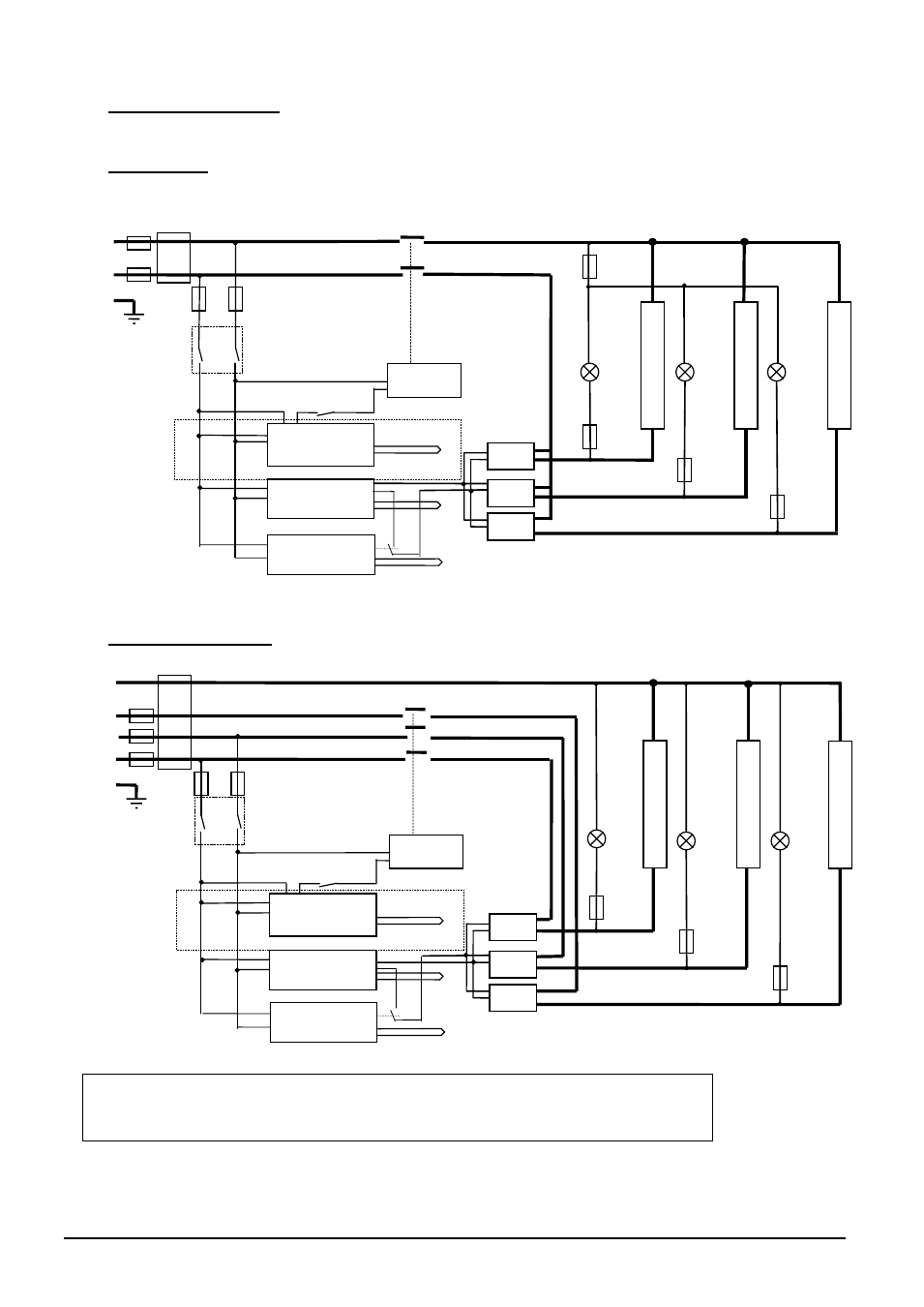
D
IAGRAMS
In these models the safety switch in the diagram is a positive-break door switch.
7.1 Single Phase
7.2 3-phase with neutral
e
l
e
m
e
n
t
(s)
e
l
e
m
e
n
t
(s)
F3
F1
N
F2
L
PE
e
l
e
m
e
n
t
(s)
Instrument Switch
coil
temperature
controller
thermocouple
overtemp.
controller
thermocouple
safety
switch
SSR
heat
on
F3
SSR
SSR
heat
on
F3
heat
on
F3
Filter
(if fitted)
if fitted
contactor
element o/temp
controller
thermocouple
e
l
e
m
e
n
t
(s)
e
l
e
m
e
n
t
(s)
F1
N
L2
L3
F2
L1
PE
Instrument Switch
coil
temperature
controller
thermocouple
overtemp.
controller
thermocouple
safety
switch
SSR
heat
on
F3
SSR
SSR
heat
on
F3
heat
on
F3
Filter (if fitted)
if fitted
contactor
note on 3-phase: depending on filter(s) fitted, there may 3 separate neutral wires
from the elements to the neutral supply.
element o/temp
controller
thermocouple
e
l
e
m
e
n
t
(s)