Fuses & power settings, Specifications – Carbolite CF 15 - CF 60 User Manual
Page 17
MF28 3.08
17
8.0 F
USES
&
P
OWER
S
ETTINGS
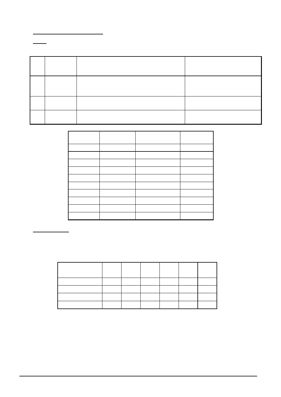
8.1 Fuses
F1-F3: Refer to the circuit diagrams.
F1
Internal
supply
fuses
Fitted if supply cable fitted.
Fitted on board to some types of EMC filter.
on-board and up to 16 Amps:
32mm x 6mm type F
other: GEC Safeclip
F2
Auxiliary
circuit
fuses
Fitted on board to some types of EMC filter.
May be omitted up to 25Amp/phase supply
rating.
2 Amps glass type F
On board: 20mm x 5mm
Other: 32mm x 6mm
F3
Heat Light
fuses
May be omitted up to 25 Amp/phase supply
rating.
2 Amps glass type F
32mm x 6mm
Customer
fuses
Required if no supply cable fitted.
Recommended if cable fitted.
See rating label for amperage;
see table below for fuse rating.
Model
Phases
Volts
Supply Fuse
Rating
CF 15
1-phase
200 - 240
80A
CF 15
3-phase +N
380/220-415/240 25A
CF 15
3-phase delta 208 - 240
40A
CF 24
1-phase
200 - 240
100A
CF 24
3-phase + N
380/220-415/240 32A
CF 24
3-phase delta 208 - 240
63A
CF 50
3-phase + N
380/220-415/240 50A
CF 50
3-phase delta 208 - 240
80A
CF 60
3-phase + N
380/220-415/240 63A
CF 60
3-phase delta 208 - 240
125A
8.2 Power Settings
The power limit settings (parameter
OP.Hi
) for these models on various supply voltages are as
follows. The figures represent the maximum percentage of time that controlled power is supplied
to the elements. Do not attempt to “improve performance” by setting a value higher than the
correct one from the table.
Model
Volts:
200V 208V
220V
380V
230V
400V
240V
415V
254V
440V
CF 15
68
63
56
51
47
42
CF 24
97
89
80
73
67
60
CF 50
87
80
72
66
60
54
CF 60
78
72
64
59
54
48