Grounding the generator, Operating the generator, Starting the engine – Briggs & Stratton Home Generator System User Manual
Page 11
11
Briggs & Stratton Power Products Home Generator System
Owners Manual
GROUNDING THE
GENERATOR
The National Electrical Code requires that the frame and
external electrically conductive parts of this generator be
properly connected to an approved earth ground. Local
electrical codes may also require proper grounding of the
unit.Whenever the unit is connected to the system’s
properly installed power inlet box, the generator is
automatically connected to the building’s grounding system.
IMPORTANT: When operating the unit as a stand-alone
generator, the unit should be connected to a grounding
rod, especially when the unit is equipped with a wheel kit.
Properly grounding the generator helps prevent electrical
shock if a ground fault condition exists in the generator or
in connected electrical devices. Proper grounding also helps
dissipate static electricity, which often builds up in
ungrounded devices.
A GROUNDING WING NUT is provided (Figure 7) to
make the grounding attachment.
Connecting a No. 12 AWG (American Wire Gauge)
stranded copper wire to the grounding wing nut and to an
earth–driven copper or brass grounding rod (electrode)
provides adequate protection against electrical shock.
CAUTION!
Do Not connect the unit to a
grounding rod at the same time it is connected to
the building’s power inlet box.
OPERATING THE
GENERATOR
CAUTION!
Never start or stop unit with
electrical loads connected AND with the connected
devices turned ON.
IMPORTANT: Always unplug the battery float charger
before starting the generator.
Starting the Engine
Disconnect all electrical loads from the generator. Use the
following start instruction steps by numerical order:
1.
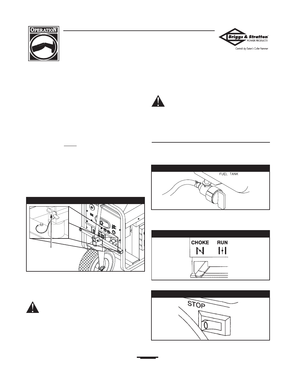
Move the fuel valve to the “On” position (Figure 8).
2.
To start a cold engine, move the choke lever to the
“Choke” position. To restart a warm engine, leave
the choke lever in the “Run” position (Figure 9).
3.
Set the rocker switch to the “On” position (Figure 10).
Figure 9 — Choke Positions
Grounding
Wing Nut
Figure 7 — Grounding Wing Nut
Figure 10 — Rocker Switch
Figure 8 — Fuel Shut-off Valve
Fuel Valve shown in
the “On” position