Balancing programs – BASELINE 225 User Manual
Page 16
12 •
Important: Always read and follow instructions.
Balancing Programs
A variety of wheel configurations can be balanced
using this wheel balancer. Read through this section, it
will help you determine which program and options are
best suited for certain wheel assemblies.
To perform a balancing cycle:
• Mount the wheel on the shaft using the most appro-
priate method. Refer to Mounting Wheel on Shaft,
pages 8 & 9.
• Remove any balancing weights, stones, dirt or other
foreign bodies from the wheel.
• If necessary, select a balancing program.
• Input wheel data correctly. Refer to Setting Wheel
Dimensions (DIM), pages 10 & 11.
• Lower hood and press
to spin wheel.
• Wait for the beep that signals the wheel measure-
ment cycle is complete.
• Use the positioning pedal to stop the wheel spin-
ning; then raise the wheel guard.
• Observe the corrective weight amount requirements
displayed for the inside and outside planes respec-
tively.
• Choose the first side you intend to balance and
rotate the wheel until the center indicator light
flashes and you hear a confirming beep.
• Attach the corrective weight at top-dead-center (12
o’clock) on the tire/wheel assembly. Refer to Attach-
ing Corrective Weights, page 14.
• If necessary, repeat the process for the other side
of the wheel.
• Lower hood and press
to spin wheel and
check balance. Your weight readings should now be
0.00.
Important: Be aware that a slight error (a degree or
two) in positioning the corrective weight on the tire/
wheel assembly can produce a residual out of balance.
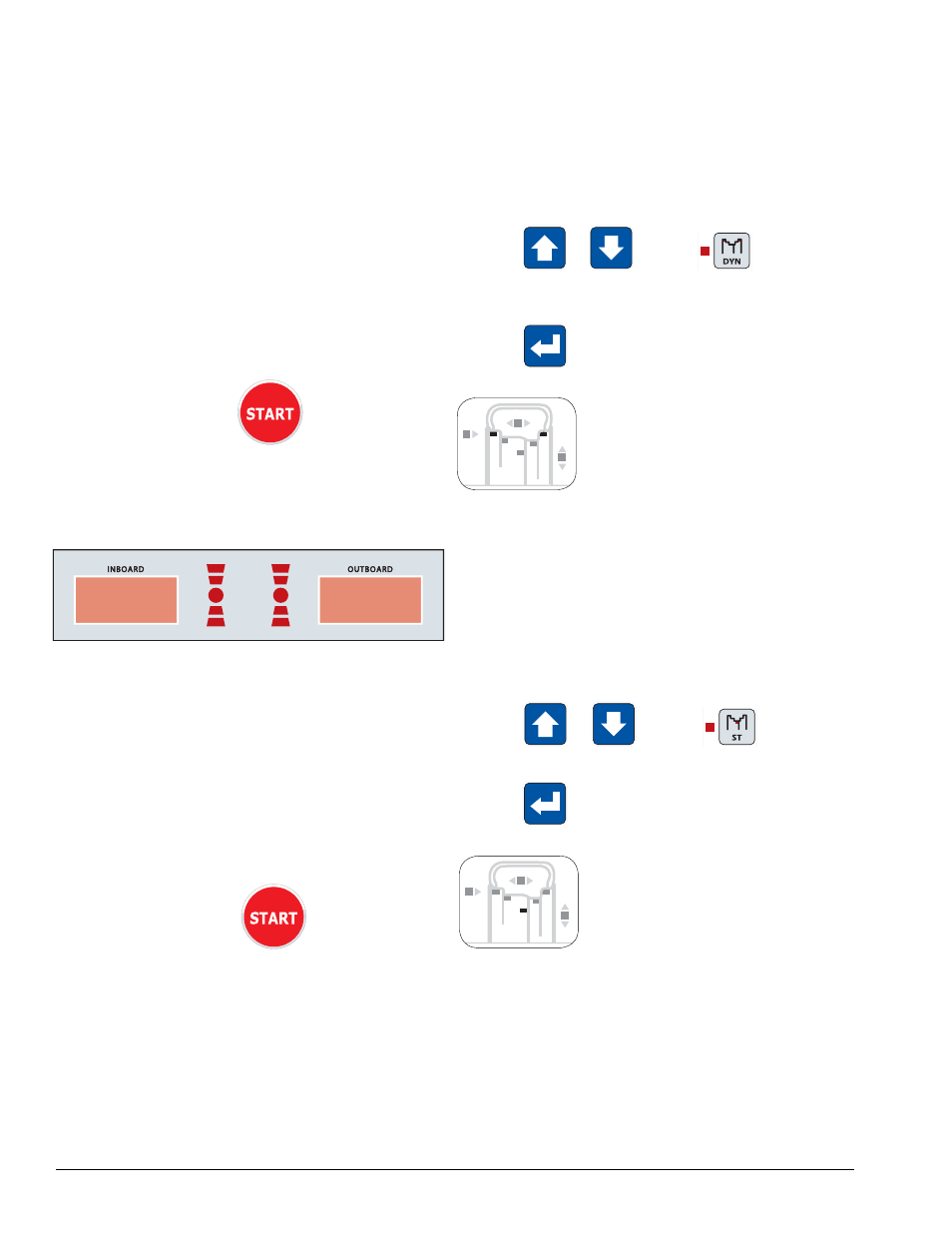
Dynamic Balancing
Choose a dynamic balance to balance a wheel using
two planes for correction. Select the weight option that
best fits the available weight locations.
Clip-on Weights - The standard default; used for most
passenger tire/wheel assemblies using the most com-
mon location for corrective weights. Clip-on weights are
placed on the inner and outer rim flanges.
•
Press
or
until the
DYN balanc-
ing program LED lights up. The two clip-on weight
LED locations light up on the rim diagram.
•
Press
to confirm your choice.
Note: The standard dynamic balancing program using
clip-on weight locations is the default setting, when the
machine is switched on.
Static Balancing
Choose a static balance to balance a wheel using one
plane for correction. Place the single corrective weight
at top-dead-center (12 o’clock) on either flange, at the
center of the rim channel or place half of the displayed
weight on both planes.
•
Press
or
until the
STATIC bal-
ancing program LED lights up.
•
Press
to confirm your choice.
Note: When in static mode, you only need to input the
DIAMETER wheel measurement.
Important: If you decide to use the rim channel for
corrective weight placement, remember you may need
to adjust the DIAMETER measurement input. Typically
you would make it 2 or 3 inches less than the actual tire/
wheel diameter.
STATIC
C1 & C2