Before you begin, Set-up – AMMCO 40111 Environmental Lathe Enclosure Conversion Kit User Manual
Page 6
6 •
Important: Always read and follow operating instructions.
Before You Begin
Receiving
The shipment should be thoroughly inspected as soon
as it is received. The signed bill of lading is acknowl-
edgement by the carrier of receipt in good condition of
shipment covered by our invoice.
If any of the goods called for on this bill of lading are
shorted or damaged, do not accept them until the car-
rier makes a notation on the freight bill of the shorted or
damaged goods. Do this for your own protection.
NOTIFY THE CARRIER AT ONCE if any hidden loss or
damage is discovered after receipt and request the car-
rier to make an inspection. If the carrier will not do so,
prepare a signed statement to the effect that you have
notified the carrier (on a specific date) and that the car-
rier has failed to comply with your request.
IT IS DIFFICULT TO COLLECT FOR LOSS OR DAM-
AGE AFTER YOU HAVE GIVEN THE CARRIER A CLEAR
RECEIPT.
File your claim with the carrier promptly. Support
your claim with copies of the bill of lading, freight bill,
invoice, and photographs, if available.
Although AMMCO’s responsibility ceases upon deliv-
ery of the shipment to the carrier, we will gladly assist
in tracing lost shipments. Our willingness to assist in
every possible manner does not make AMMCO respon-
sible for collection of claims or replacement of lost or
damaged materials. Shipping damage claims will not be
handled under warranty.
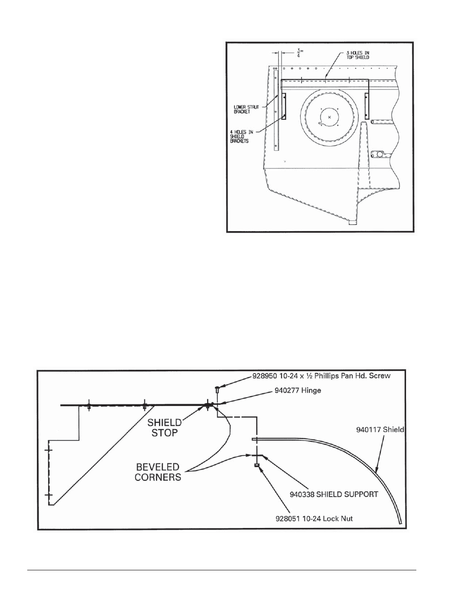
Set-up
Place the shield top and side assembly as shown.
Mark the seven hole locations on the plastic base using
the top and side assembly as a fixture. Drill seven holes
using a 9/32-inch diameter drill bit. Place 1/4-20 screws
through the top and side assembly and the plastic base
from the front side. Attach washers and nuts from
the rear of the unit and tighten. Place a #10-24 screw
through the top side of the hinge and through the cor-
responding hole in the plastic shield. Position the shield
support so that its beveled corners are facing the bev-
eled corners on the mating shield stop. Attach nut to
screw. Assemble the remaining five screws and nuts
before tightening any of them.
940111 & 95000223 Kits Only
940111 & 95000223 Kits Only