American Lighting 12TL-RGB Series User Manual
Led rgb kits
LED RGB Kits
Installation instructions for 12TL-RGB Series
READ ALL OF THESE INSTALLATION INSTRUCTIONS BEFORE INSTALLING THE FIXTURE. FAILURE TO FOLLOW
INSTALLATION INSTRUCTIONS AND ALL APPLICABLE ELECTRICAL CODES WILL VOID THE PRODUCT WARRANTY.
WARNING:
These products may represent a possible shock or fire hazard if improperly installed or attached in any way.
Products should be installed in accordance with these instructions, current electrical codes and/or the current
National Electric Code (NEC).
WARNING:
Disconnect supply power from the source prior to installation. This product must be installed by a person
familiar with the construction and operation of the product and the hazards involved, and in accordance with
current electrical codes and/or the current National Electric Code (NEC). Consult a local licensed electrician if
you are not sure about the installation. Do not mount or support the strips in a manner that can cut the cover
or damage the cords’ insulations. Do not restrict strip lights’ ventilation.
CONNECTING AND TESTING:
NOTE: This product is polarized! This means that the power supply will need to be attached “right-side up” for
the RGB strip to light properly. Test which way is the right side up in the following manner before proceeding
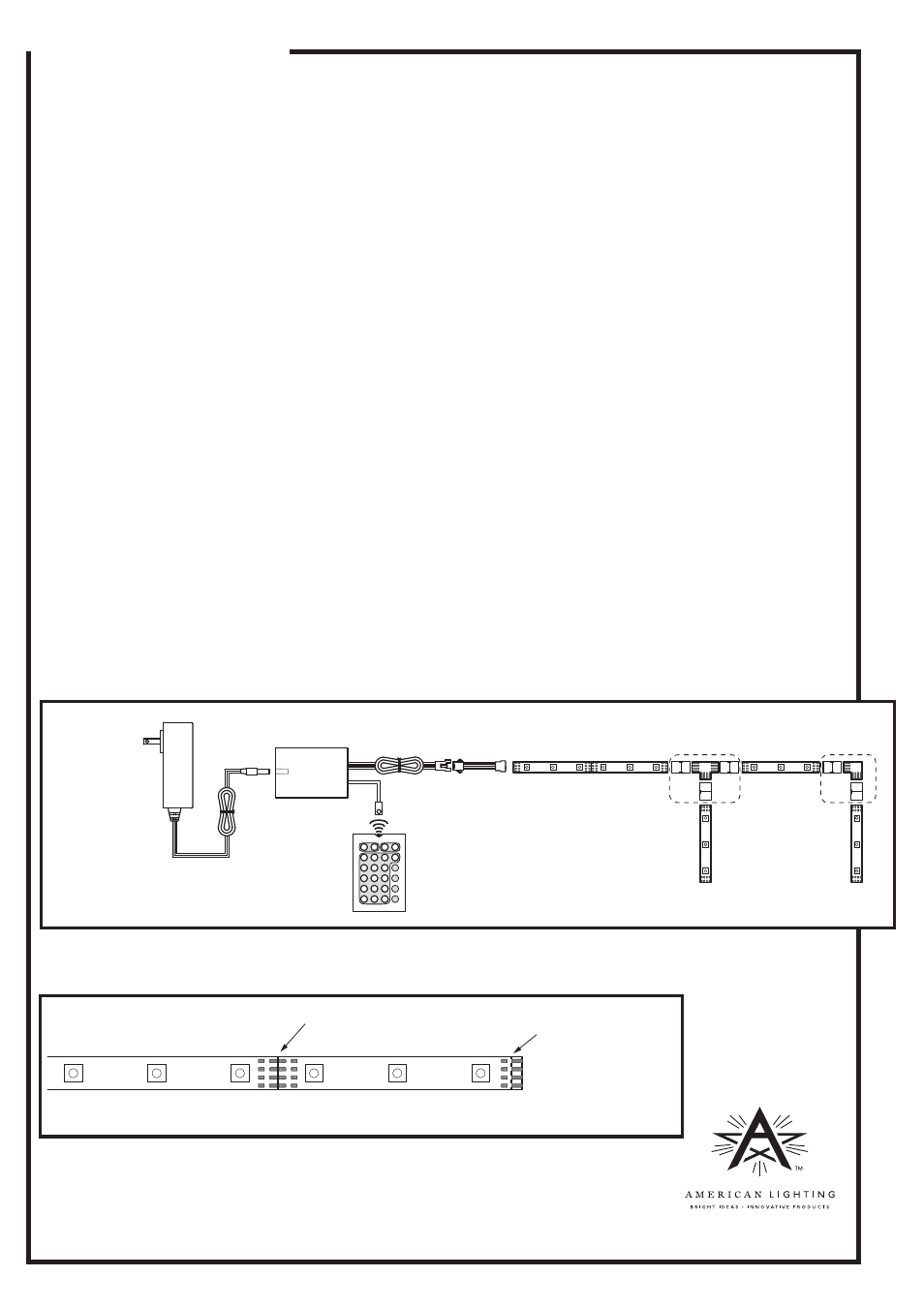
and before adhering to any surface: (See Figure 1 and chart on reverse for remote control presets/options)
1. Attach the DC power supply (DC jack) to the RGB control box/receiver (female port).
2. Attach one end of one of the RGB strip to the flat connector on the lead wire/adaptor cable.
3. Plug the power transformer/adaptor into a 120V AC outlet.
4. Use the “ON” button on the handheld remote control to test if the first strip will light up. When using the
remote for the first time, check that the lithium battery is in place and remove any plastic protection
sleeves that may be alongside the battery.
5. If the RGB strip lights up, the lead wire is connected correctly. Otherwise, if it does not light up, remove the strip from
the power cord, turn lead wire’s connector up-side down and insert the same end of the RGB strip.
6. When the RGB strip lights up and operates with the handheld remote control, note which orientation
works and proceed with the installation. If cutting RGB strips to use L, T or splice connectors, continue
with the polarity test so that all sections light up, then proceed. See Figures 1 and 2 and steps 5-7 on
reverse for connecting accessories. Note: The end of the last strip does not require an end cap.
WARNING! Risk of fire:
Do not exceed maximum run of 8.2 feet (2.5m) connected to a 1.5A transformer/
adaptor or 16.4 feet (5m) connected to a 3A transformer/adaptor.
RV-1330
©2013 American Lighting
Denver, CO 80231 Made in China
www.americanlighting.com
Figure 2
Figure 1
12V 1.5A Plug-in
transformer/
adaptor
RGB control
box/receiver
and
handheld
remote
control
Lead wire
adaptor
cable
DC jack
7. To cut RGB strip light, use scissors and cut squarely along cut mark. See Figure 2.
8. To prepare cut strip for accessories, cut off clear jacket up to line shown below. See Figure 2.
Cut mark
Cut off clear jacket up to
this line to expose
conductors if using
accessories
RGB strip is cuttable every 3 LEDs at cut mark only
RGB
strip
‘T’ connector
‘L’ connector